At the end of my last post in this series, we had added the top plates and roller holder. This post focuses on the cables and feeder components, covering issues 64 – 67 of 3D Create and Print by Eaglemoss Technology. If you’ve skipped a part of this series you can start from the beginning, including details of the Vector 3 printer I’m building on my 3D printer page.
-
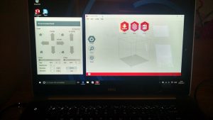
Testing the connection Cables: Issue 64 comes with your country specific power cable, and issue 65 comes with the USB-component cable. I initially wasn’t going to even open these as I knew there’d be no chance of printing. However, there was a very important step – validating that the computer could talk to the printer. As my surface doesn’t have any USB ports, I had to break out the Dell XPS. The software from Eaglemoss requires .Net 3.5 so if you’re on Windows 10 then you’ll get an error message and need to enable this. Microsoft have a helpful guide on how to do this if you’re not sure. With the v3 software installed, the printer connected to the mains, the USB cable connecting them both and the power turned on, my laptop was able to “see” the printer. This was a great step forward.
-
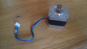
Feeder motor and gear Feeder motor: Issue 66 comes with the feeder motor. This is a simple but slightly fiddly step to attach the feeder gear and use the grub screws to hold it in place. Was it really a year ago I was doing this for the axis motors? Be careful as you open the parts as, despite the sellotape, the grub screws can easily pop out and be lost. You will also need the extra small allen key from those early issues (or the toolkit if you were an early subscriber. Make sure the gear is aligned with the top of the motor spindle and screw in the grub screws using the allen key.
-
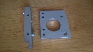
Print head mounting plate orientation 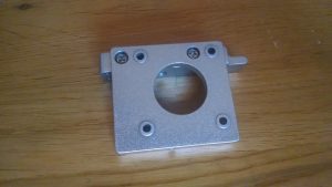
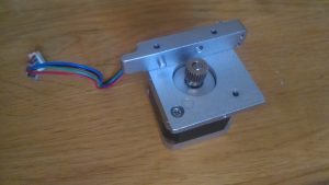
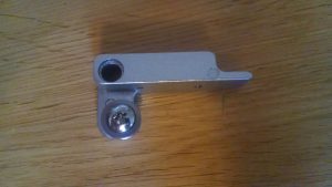
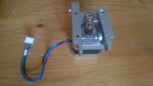
Print head plate – screw positions Print head holder and feeder: Issue 67 comes with the parts for the spring loaded feeder mechanism. Make sure the print head mounting plate is the correct way up (see picture) and attach the print head holder with the bolts. Fix the mounting plate to the feeder motor with the third of the 5.5mm bolts, making sure the holder is on the same side as the motor wires. Attach the feeder bearing to the bearing block with the 8.5mm bolt, making sure the bearing rotates freely. Add the axle socket into the feeder bearing block and fix with a 15.5mm bolt. Even fully tightened the bearing block should move against the motor gear. Add the spring to the retaining plug and fit the other end of the spring to the on the inside of the print head holder. Add a bolt to secure the spring through the bearing block. Tighten the bolt fully to tension the spring. The bolt will not go fully into the retaining plug – if you look closely at image c in step 6 in the magazine, you can see part of the bolt between the bearing block and retaining plug, but it isn’t clear from the text.
So four more issues and we’ve tested connection to the computer and built out the feeder motor and bearings, with more parts for the printer head in the next issue.