At the end of my last post, we had started to build the x-axis assembly and got both shafts and the bearing block in place. This post looks at adding the timing belt and the x-axis motor, covering issues 20 to 23 of 3D Create and Print by Eaglemoss Technology. If you’ve skipped a part of this series you can start from the beginning, including details of the Vector 3 printer I’m building on my 3D printer page.
You’ll need to dig out the motor test circuit board and AC adaptor to completed these steps and they are very similar to that for the y-axis so should be fairly quick for you to go through. If you’re a subscriber then this drop also comes with four packs of filament in different colours, which you’ll just have to keep somewhere safe until we’re in a position to use them.
-
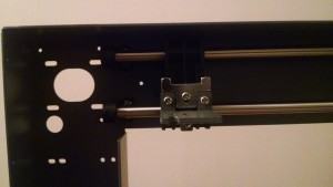
X-axis bracket and timing belt holder X-axis bracket: This comes in two parts and, using the knowledge from the y-axis assembly, we know that we’ll have to undo one of these parts to attach the x-axis timing belt. So if you already have issue 21, you may want to just attach the bracket until you’re ready to add the belt at the same time. This is simply a case of screwing the two parts to the bearing block.
- X-axis timing belt: If you’ve already attached the belt holder then slacken the screw to loosen this. Slip the belt over the bearing at the end of the assembly and then feed the belt through the bearing block, lining up the teeth on the belt with the belt holder. Tighten the screw.
- X-axis limit switch: Push the limit switch onto its holder, making sure you have it on the right way round. Don’t worry if you get it wrong – use a flat screwdriver to prise it off gently – but it’s easier of you don’t have to do this. Untie the wires and feed the red and black wires through the guard clips and then feed the rest of the wire through the round hole in the main frame to keep it out of the way. Screw the switch holder to the main frame with the two screws. The timing belt does get in the way here so you may want to do this step before the timing belt, but it’s not critical.
-

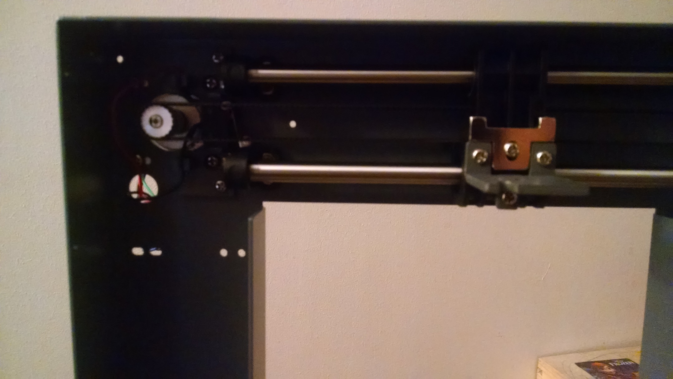
X-axis motor, switch and timing belt X-axis motor: The final step in this set of parts is the motor and its test, just as we did for the y-axis. So dig out your test circuit board and AC adaptor. You’ll also need the small allen key that came with the y-axis motor (or the tool kit if you’re a subscriber). Connect the timing gear onto the x-axis spindle ensuring the grub screw attaches to the flattened side of the spindle. Slide the motor through the main frame looping the x-axis timing belt over the spindle. Loosely screw the motor to the main frame and check that the belt is tight. You may need to adjust the position of the gear on the spindle to prevent the timing belt from coming off as the assembly moves. Once you’re happy, tighten the screws, making sure the limit switch wires are well out of the way. Do the manual movement test and make adjustments as necessary. Get the motor test board, ensuring it is disconnected from the y-axis assembly and attach both the limit switch wires and the main motor. It can be a bit tricky to yet the y-axis wires out of the circuit board – don’t be tempted to pull them out by the wires – hold the white plastic and gently ease them out. Connect up the x-axis motor and switch and run the test. If you need to make any adjustments, disconnect the power completely first and ensure you follow all the safety precautions in the magazine.

And here’s the final test: