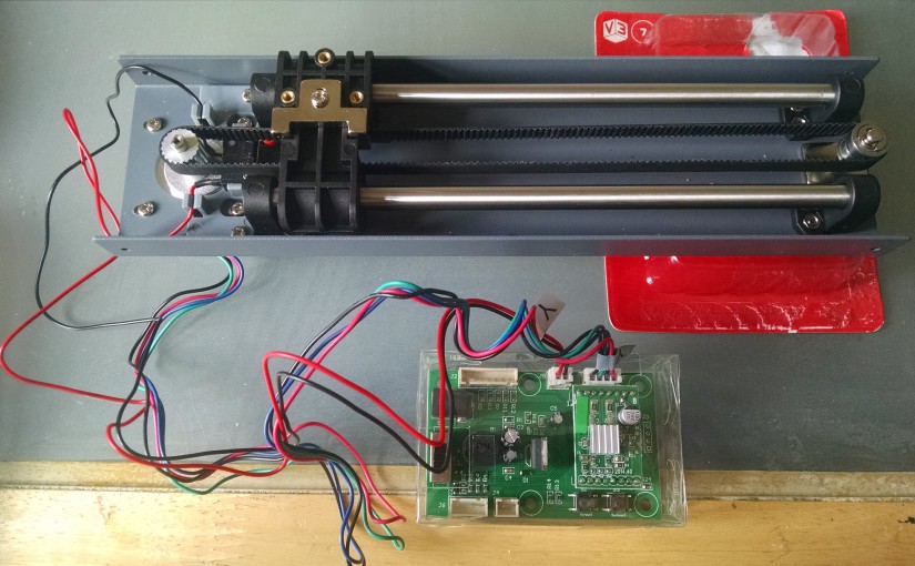
Following from building the Y-axis assembly of my 3D printer, this post covers the fitting of the motor and the circuit boards to test, using the pieces in issues 7 to 10 of the 3D Create and Print magazine. It’s a good job that, even though this is a “weekly” magazine, the issues arrive in sets of four as otherwise I imagine it could be very frustrating waiting, not able to add to the printer, until issue 10.
I don’t actually see why this stage was any different to the earlier steps – if the pieces had been delivered in a different order then there would have been no need to wait until the 10th issue before starting. I can only assume that someone may have been tempted to power it all up before it was ready, which is why the motor itself is the last piece from this stage to arrive.
This is the first issue to come with important safety notices. I would have expected some sort of notice regarding eye protection when adding the e-clip to the bearing due to the number of times this small sharp piece of metal flew off while trying to fix it… As a glasses wearer, I was fine although I think my lenses may have another scratch in their apparently scratch-resistant coating. (I suppose that’s unfair, scratch-resistant does not mean scratch-proof and I doubt that part of their testing was to have small shards of steel thrown at them…). However, please ensure that you follow the safety precautions:
- Do not connect the AC adapter to the test board until steps 1 to 5 below have been followed
- Keep the motor tester board inside the protective box at all times
- The motor can be hot so make sure it is never placed on a surface that could be damaged by heat
- Never run the motor without it being bolted to the Y-gantry cover as this acts as a heat sink – failure to do so could overheat the motor
- Never run any of the components near water or allow them to get wet (if you need to be told this then you probably should not be allowed near a screwdriver!)
- Keep fingers, hair, loose clothing etc away from all moving parts
- Switch off the power immediately should anything become trapped
- As soon as the test is complete switch off the motor tester board and disconnect the power adaptor to prevent overheat of the board
-
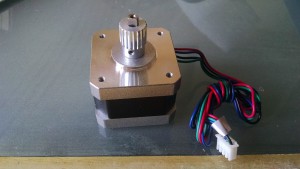
Y-axis motor Timing belt gear: These parts were from issue 10. Slide the gear onto the motor ensuring the screw hole is aligned with the flat side of the shaft. The diagram is a little misleading here as it shows the flat area only halfway down the shaft rather than all the way to the motor. Screw into place with the grub screw using the allen key supplied (a duplicate of the one in the tool kit). This is far less stressful if you out the screw on the long end of the allen key and turn the short end, even though you have to do more turns. Make sure the screw stays aligned with the flat side of the shaft while you tighten the screw.
-
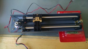
Y-axis motor fitted to timing belt Y-axis motor and timing belt: Fit the motor to the Y-axis gantry (from issues 1-6). Unless you have someone to hold the other end of the gantry you’ll need to support it with something until you have everything screwed in. I found the parts box from issue 7 to be about the right height 🙂 (although take the circuit board out first so you don’t damage it …). Make sure the wires from the stop switch are out of the way and the y-motor wires are pointing out of the side of the gantry (see photo). Make sure the timing belt is still engaged with the bearing at the other end of the gantry and ease the belt over the teeth of the gear. Add the four bolts loosely and then slide the motor outwards to tension the belt before tightening the bolts fully
- Manual movement test: I found when gently sliding the bearing block that the movement was a little jerky and that the timing belt did start to come off the top of the gear. I loosened the belt holder a little as it suggested and realigned the belt and then retensioned everything by loosening the motor screws, pulling the motor outwards and retightening. I’m still not happy with the smoothness but I think this is down to the y-shafts and the bearing block rather than the belt.
-
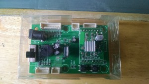
Motor driver board Motor driver board: Take the lid off the temporary plastic box for the motor driver board and take the test board out of its anti-static packaging, avoiding touching the pins. The instructions don’t really mention this, but if you’re wearing clothing prone to static you may want to ensure you are earthed before you continue :). Carefully align the test board with the motor board – it will only fit one way due to a missing pin – and slide into place. Then replace the lid of the temporary box.
-
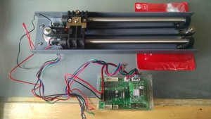
Motor tester board connection Motor tester board connection: Add the wires from the limit switch into the socket on the board marked J5 (make sure this is the right socket!). If you haven’t already, un-knot the motor wires and slide the 4-pin plug into socket J9 (again, make sure this is the correct socket!). Both of these plugs will only fit one way. I found the 4 pin plug particularly tricky to get in, so took the lid off the box (making sure the wires were fed through the hole) so that I could get a better angle to ensure the plug was in firmly.
- AC adapter and test of Y-axis: Another safety warning here – make sure only to use the adapter supplied with the kit. Plug the adapter into the board, make sure that the plug is in the ‘off’ position and plug the adapter into the power socket. Turn the switch to ‘on’. A small light will come on and there will be a faint whirring noise. There are two buttons – one to go forward and one to go backwards – these are quite small and difficult to get at through the temporary box . Check that the bearing block moves smoothly in both directions then turn the board off and disconnect the power. Even though the movement was a little jerky manually – it was quite smooth when powered by the motor (ignore the stop-start in the video that is me not pressing the buttons properly).
So, we’re now at the end of issue 10 and have a working y-axis gantry and motor. The next few issue finish up the y-axis assembly and start the x-axis, which I’ll cover in the next post.
