At the end of my last post in this series, we had added the power switch and control unit covers and the look of the main part of the printer was starting to come together. This post focuses on the USB, microcontroller and motor boards covering issues 52-55 of 3D Create and Print by Eaglemoss Technology. If you’ve skipped a part of this series you can start from the beginning, including details of the Vector 3 printer I’m building on my 3D printer page.
Due to some of my OU studies and work, I figure I’m now 6 months behind in this build so please accept my apologies if you’ve been waiting on my posts to do your own builds. So, when I finally opened the pack, I initially panicked to see that there were two issue 55 parts that came in my pack. On checking the magazines, they had different part numbers but were identical in every respect as far as I could tell from the magazine. As such, I have used these parts as supplied. If this turns out to be a problem I’m sure I’ll find out later…
-

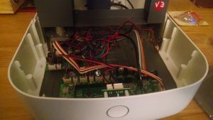
USB board in place next to the power adapter USB board: Issue 52 is another simple addition, although a little fiddly due to the existing parts. Line up the USB board into the hole at the back of the printer. There are two fixing channels to hold the board that are very tight. This combined with the power adaptor wire exactly where you’d want to put your hand to push the board makes this very tricky to align. I found that getting the first millimetre or so in the channels and then gently pushing with one of the files at 90 degrees to the board gave the gentle pressure I needed. Then fix the board in place using the supplied screws. Again, both the board itself and the power wire really get in the way here. Had I known the detail of this part, I would have done this step before attaching the power adaptor from issue 51. Once attached, push in the 5 wire cable making sure that the red wire is closest to the power adapter.
-
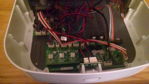
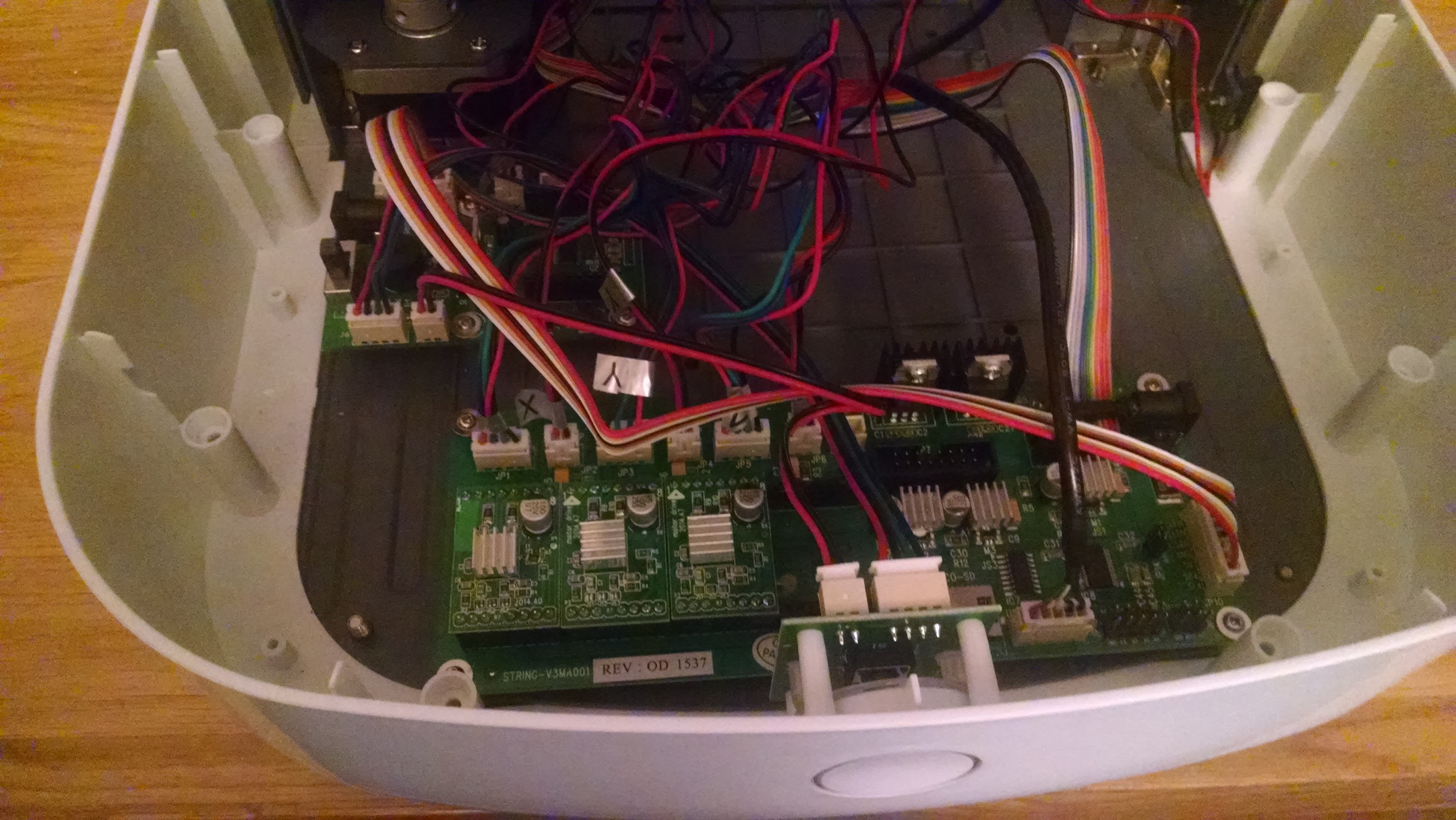
Main microcontroller board and motor test board fitted to the base Main microcontroller board: Issue 53 is a more complicated build – first one in a while that has 11 steps. To start with, the motor tester board needs dismantling. Take the motor tester board and gently remove the motor driver board and fit it to the main microcontroller board. You can’t go wrong here as with one side having 7 pins and the other 8, it will only fit one way. Just don’t bend the pins :). Attach the motor test board to the front of the lower cover. Make sure that the motor driver board is the correct way around. Then attach the main microcontroller board to the front lower cover using the remaining 4 screws. Connect the 7 wire cable in socket j2 on the tester board and JP10 on the microcontroller board. The colours on the wires didn’t match the image for me, but it didn’t matter as they all line up. Then connect the hood limit switch to the motor tester board socket J5. Next, connect the 4 wire from the from the power switch into the motor tester board J6 and then the two wire from the power switch into J4. Pass the wires for each axis unthe the main frame and attach to the board left to right, for X, Y and Z axes. Plug in the 10 wire ribbon cable from the heater and heat sensor into JP8 on the microcontroller board and then finally the black insulated wired from the USB board into the USB socket. You’ll probably have a slightly messy set of wires now even if you’ve been careful about threading them through
-
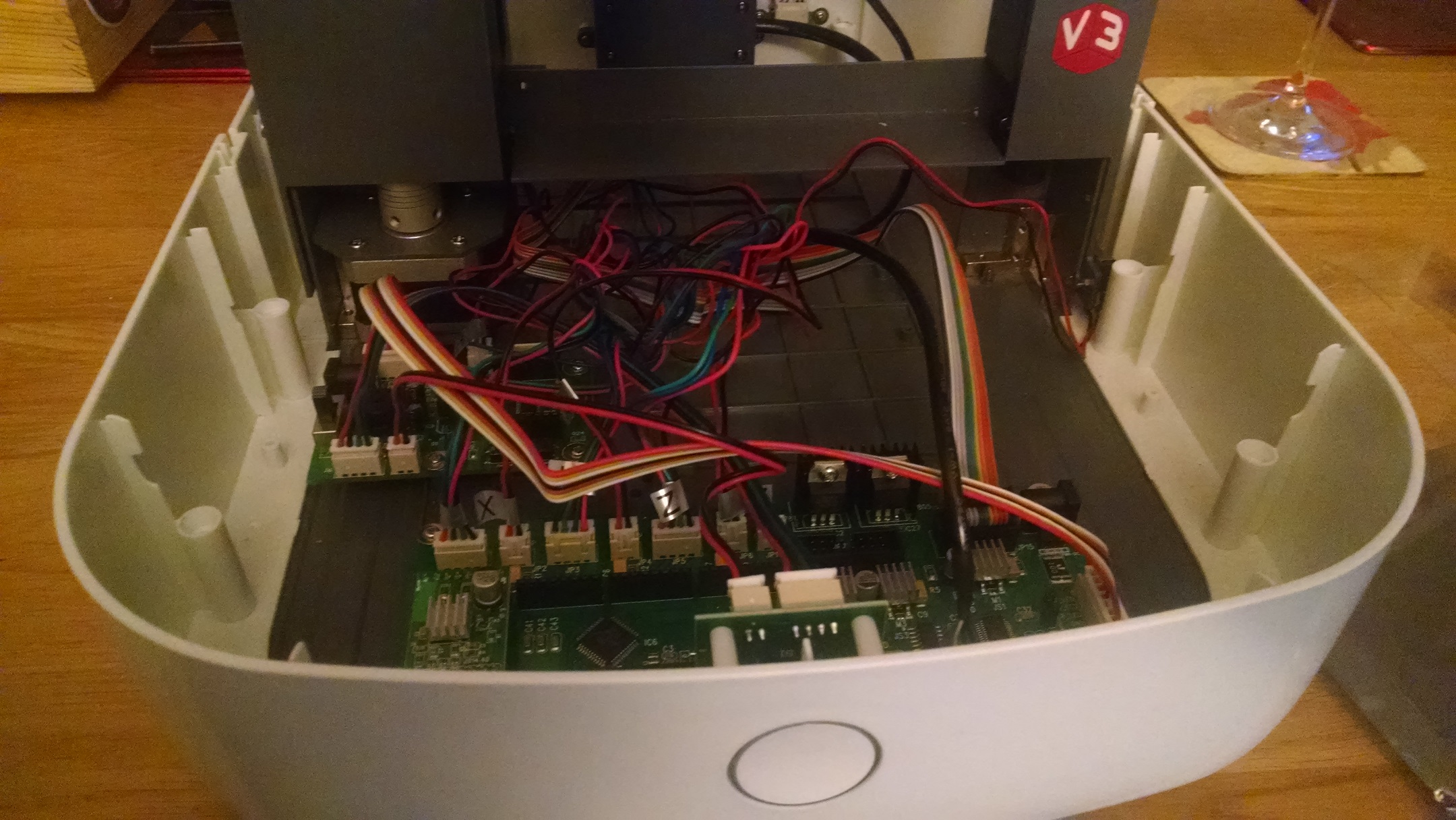
Microcontroller board with 3 of 4 motor boards fitted Motor driver boards: Issues 54 and 55 come with two more motor driver boards. This is no more complicated than opening the packet and plugging the boards onto the main microcontroller board.
And that’s it for these four issues. It’s great seeing the wires all connecting up and it does feel really close. However, as I am sever months behind in my build, I know that even another 16 issues doesn’t get me to a functional printer…. but surely it can’t be long now?