At the end of my last post in this series, we had added the lower cover and the hood limit switch, which didn’t feel like much progress. This post focuses on the control unit covers and power switch covering issues 48 – 51 of 3D Create and Print by Eaglemoss Technology. If you’ve skipped a part of this series you can start from the beginning, including details of the Vector 3 printer I’m building on my 3D printer page.
Despite the delay in opening this set of four issues, I was very excited to see these next parts. The sight of the iconic white base covers and power switch immediately gave me the feel that the printer would look a lot more complete after adding them. You may want to read through before starting, as I found some parts were easier in a slightly different order.
-
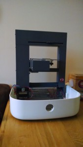
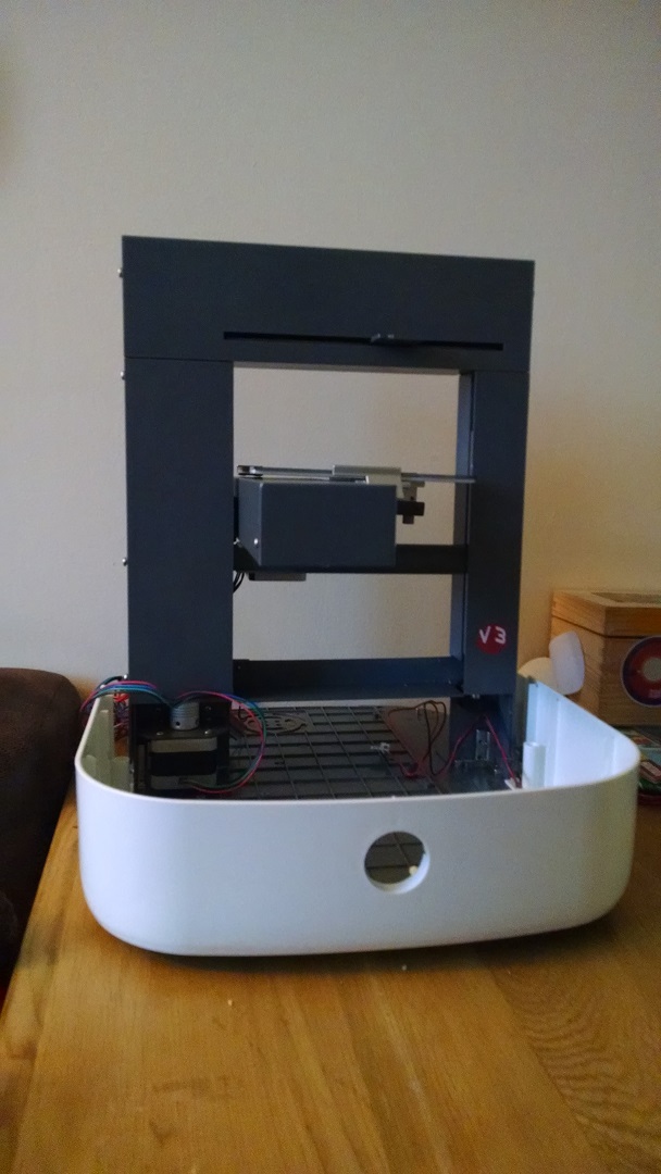
Front cover added 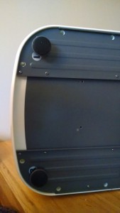
Underside of the printer showing the screw points Control unit front cover: Issue 48 gives the front cover for the base of the printer. If you struggle with adding extra pieces at an angle then you might want to do the power switch from part 49 first before attaching to the base. This comes with support sprues to prevent damage in transit and these need to be removed before we can do anything else. If you got the tool kit with the initial subscription, there’s a pair of side-cutter pliers that can do this job. Snip closely to the edges of the moulding sprues. Once you’re happy that the edges are smooth enough (you may need a small file to do this), you can fit the cover to the main body of the printer. Rather than turn it on the side as the instructions suggest, I found it was easier to sit the cover on top of the base and align first, then gently turn on its side. You can then fix the cover. Rather than 6 screws, I found there were only 5 holes available, I wasn’t too fussed by this as everything else was all aligned. Just make sure that none of the wires from the limit switches or motors are caught in the cover before you tighten the screws.
-
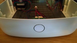
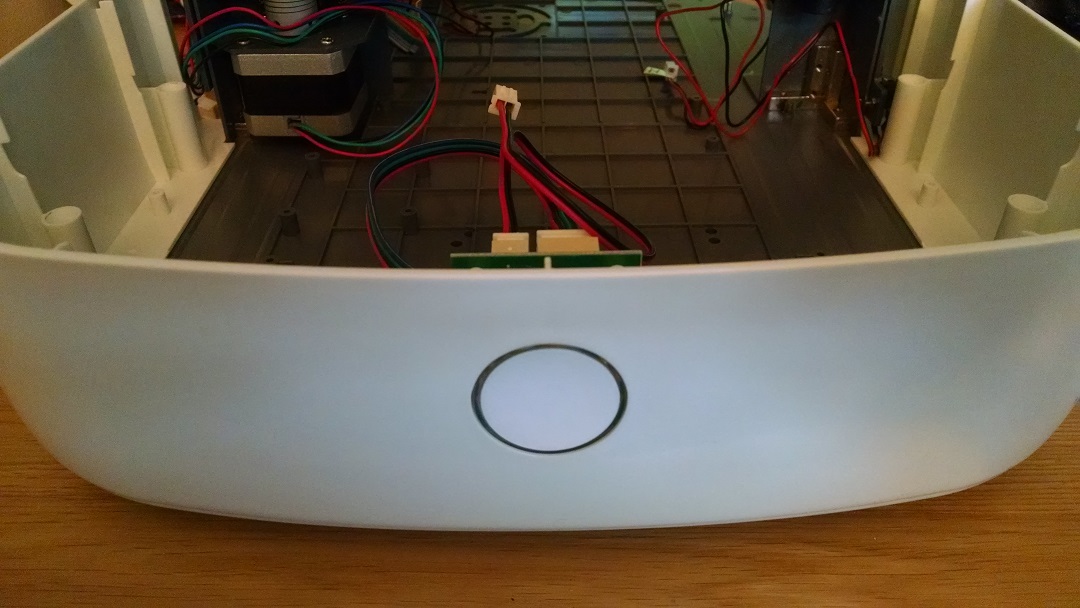
Power switch fitted 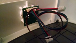
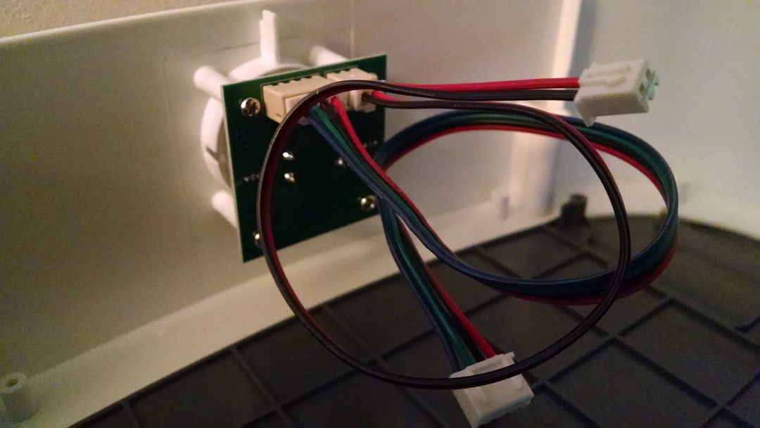
Power switch circuit board added Power switch: Issue 49 provides the power switch and connectors that attach to the front cover. This is perfectly simple to add at an angle, but you may want to do this step before attaching the cover. I did the cover first, so will assume you’ve already attached this to the base. Slide in the power button into the hole in the front cover. This will only go in one way. Add the circuit board – there is nothing to support this, so you will need either an extra pair of hands to hold it in place while you attach the screws or (as I did) loosely attach the top screws and then realign the circuit board to get all four in, then tighten. Click in the wires, these will also only go in the correct way.
-
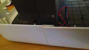
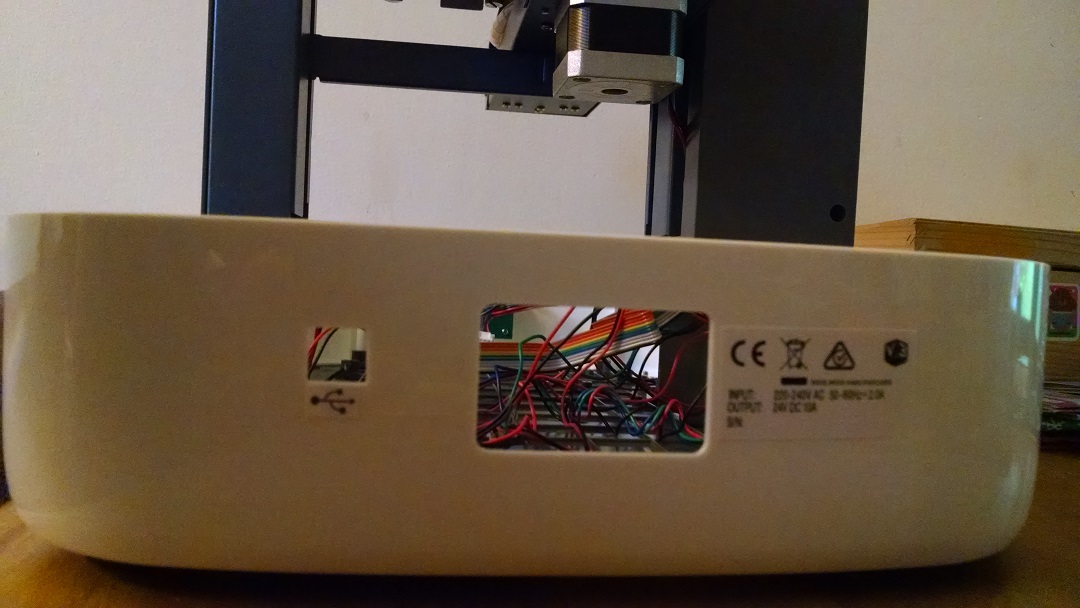
Slightly ill fitting covers 
Back cover fitted Back cover: Issue 50 comes with the back cover and is pretty similar to add as the front cover. Remove the moulding spues with the pliers and smooth the edges. Align the cover on the back and slot against the front cover. I found this alignment a little fiddly – if I got one side in the other popped out. After screwing the cover to the base, the sides still didn’t fit together as cleanly as I’d like. I’m hoping that this will be resolved as the build progresses. If not then I’ll add some glue ;). Last step was to add all the compulsory warning stickers and make it feel like we’re close to a working machine!
-
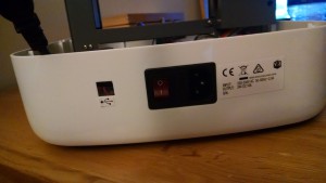
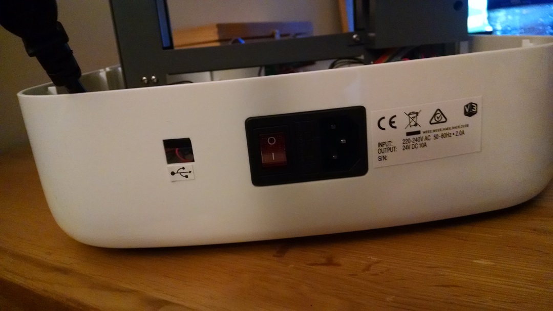
Power switch added to rear cover Mains power socket: Issue 51 comes with a very subtle mains power adapter. This slots easily into the larger hole in the back cover. Adding the screws is getting tricky now as there are so many other parts of the printer in the way of getting the screwdriver at the right angle. With these four screws in, this is the end of this set of parts.


So we are four parts further on and it’s definitely feeling close now. The next set comes with USB connectors and the motor boards, which I imagine will fill in the base of the printer.