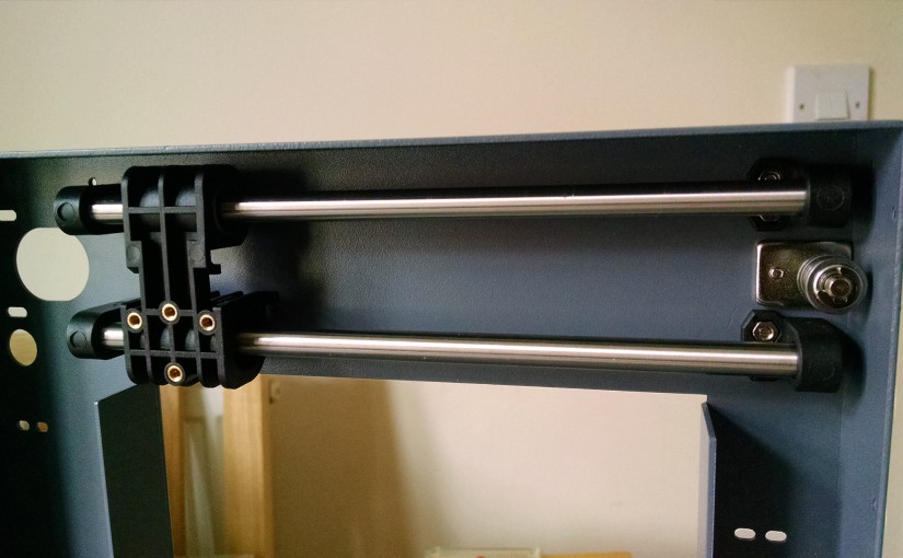
At the end of my last post, we had a completed y-axis and had also built the main frame of the printer, this post looks at building the x-axis assembly, covering issues 16 to 19 of 3D Create and Print by Eaglemoss Technology. If you’ve skipped a part of this series you can start from the beginning, including details of the Vector 3 printer I’m building on my 3D printer page.
While this is mainly an exact copy of the steps that we undertook for the y-axis, we are working directly on the mainframe, which presents its own challenges. There are a few tips I suggest to make life a little easier for yourself, especially if you’ve been saving parts or have received several issues in the same drop.
- New binder: With issue 16 comes the need to start the new binder – this hasn’t got any less fiddly than the first so if you need a reminder of how to do it, jump back to Part 1.
-
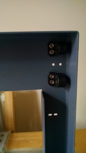
Going off-book – the two bases at one end of the frame X-shaft and fixing base: This takes us all the way back to issue 1 of the magazine when we were looking at this for the y-axis. While the instructions say to fix the shaft at both end with the bases, we know we’ll have to unscrew one of these to attach the bearing. Since I had the next few issues, I read ahead to ensure my hypothesis was correct (it was) and then went “off-book”. I used both fixing bases from issue 16 at one end of the main frame rather than firmly fixing the shaft into place. At this point the easiest way to attach the bases is to turn the whole frame onto its back and use the corner of a table to support the weight while giving you access to both sides of the frame to screw on the bases. This will ensure you can attach them without the frustration of dropping the screws and nuts.
- X-shaft and fixing base: Issue 17 tells us to attach the second shaft and fix it at both ends, but since we know where this is going and we already have two bases at one end of the frame, I completely ignored this step and opened issue 18…
-
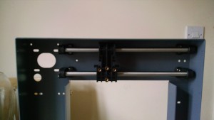
X-axis bearing and fixing bases completed and back level with the instructions 
Using the table as a support while fixing the x-axis shafts and bearing X-axis linear bearing block: Issue 18 includes the bearing block that we know slides onto both x-axis shafts. So rather than having to unscrew anything we can attach the shafts to the bases, slide on the bearing block and then attach the two new bases that came with issue 17. At this point, you are back on track with the instructions but haven’t had to unscrew anything. I noticed at this point that the x-axis bearing block seemed looser on the shafts than the y-axis had – not sure if this is intentional or not at this stage.
-
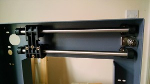
Timing belt bearings added to the frame X-axis timing belt bearings: Issue 19 gives the bearings with the same fiddly e-clip as we saw in issue 5. Eye protection may be needed here, although having done this once I did find this easier the second time round. Then it was just a case of screwing the bearing base to the main frame and 4 issues worth of parts was done.
So we now have the startings of the x-axis assembly on the main frame and we still have the complete y-axis stored safely as a separate part. I’m looking forward to getting these two bits connected together!
