At the end of my last post in this series, we had added the z-shaft support and top and side covers, giving all three axes attached to the main cover and covered. This post focuses on the lower covers and the hood limit switch covering issues 44 – 47 of 3D Create and Print by Eaglemoss Technology. If you’ve skipped a part of this series you can start from the beginning, including details of the Vector 3 printer I’m building on my 3D printer page.
On first appearances, this looks like another straightforward build – but I’ve learned that sometimes simple steps can be more fiddly than you’d think with this printer! If you’re a subscriber then this delivery also comes with the third binder, which we’ve been waiting for for a while.
-

Covering the cables 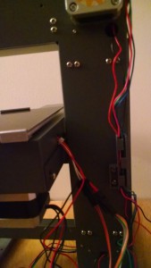
Tidying the x-axis cables Main frame rear cover: Issue 44 comes with a cover and a cable holder. You may remember some of the difficulty in getting the cables into the holder for the heater cable from issue 37. The first step is to bolt the cable holder to the main frame, ensuring that you get the holder the right way up. Thread the wires from the x-axis (the limit switch and the motor – 6 wires in total) through the holder. This is easiest if you do it one wire at a time. Once the wires are tidied away, then you can add the cover using the remaining 4 bolts. The two left most bolts are the most difficult to get in place securely as you can’t see if the bolt is aligned. Makes sure that all of the wires are enclosed and are guided through the opening at the bottom of the cover.
-
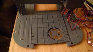
Rear lower cover Rear lower cover: Issue 45 comes with the rear cover that, counter intuitively, needs to be bolted from underneath the main frame and with the textured surface uppermost. At this point you may find that the main frame supports are not perfectly parallel – if this is the case, you may find that they have a little bit of movement so that you can get the bolt holes to align. If not then you may have to loosen the main frame supports slightly to allow you to realign.
-

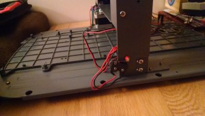
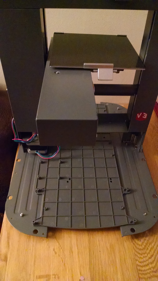
Front lower cover Front lower cover: Issue 46 comes with the front cover and this is the same process as for the rear cover, ensuring that everything is aligned before the bolts are completely tightened. The main issue with this part of the build is making sure you pick the printer up carefully – not all of the parts can hold its weight.
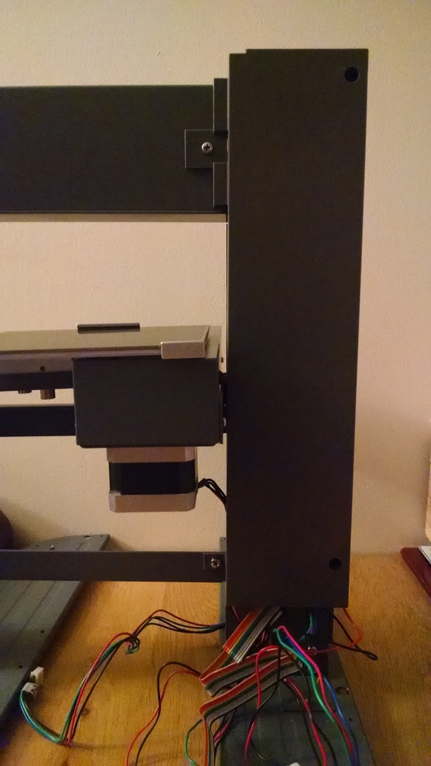
- Hood limit switch: Issue 47 comes with the limit switch for the printer hood – an essential safety feature that will stop printing if the hood is raised. Bolt the switch to the frame (the side with the V3 logo) at a slight angle, ensuring the connecting part of the switch is toward the centre of the frame. The build instructions include the tip of holding the nuts with a pair of pliers while you tighten the bolts – this is pretty essential and fairly easy (if you have a pair of pliers to hand!).
Hood limit switch


So with three more covers and a safety switch fitted the printer is looking one step closer, although all the new bolt holes in the base indicate how much more there is to come! All that remains is to bind 15 of the 17 issues I have unbound and wait a few more weeks for the next parts!