At the end of my last post in this series, we had added the top cover, filament guide and hood. This post focuses on the rear cover and some additional maintenance, covering issues 82-84 of 3D Create and Print by Eaglemoss Technology. If you’ve skipped a part of this series you can start from the beginning, including details of the Vector 3 printer I’m building on my 3D printer page.
It’s been a while since my last post where I was hoping that I would have a post on my first print. However, after reflashing the firmware as advised, I’ve struggled to get the laptop speaking to the printer. There are things to be done that I’m working through and as soon as I have a solution I will post it up. If you’ve got to this point and your printer is not working, please do not panic, I’ll put up diagnostic steps and solutions as soon as I have them.
- Print head connector board- change of switch: The first change I needed to make before progressing is that the fan on the print head ran constantly rather than when the software controlled it. This was controlled by the print head connector board form issue 70. Given how careful I was in ensuring that the switch was in the correct position as detailed in the magazine, I surmised that wither the board has been soldered incorrectly or the instructions were wrong. After a bit of googling from forums where other people hadn’t mentioned this, I did find one other person with the same problem who change the switch and the fan worked perfectly. If your fan runs continuously when the unit is powered then you may need to follow these steps.
- Remove the print head cover – this should just be a lift off if you are at the same point as this blog, otherwise work backwards to release the cover
- Lift out the filament tube
- Unscrew the top of the printer with the four screws and put safely to one side
- Unscrew the print head cover with the single top screw to expose the circuit board
- Move the switch to the other position
- Power up the printer and ensure that the fan only runs when required by the software
- Replace all the other parts
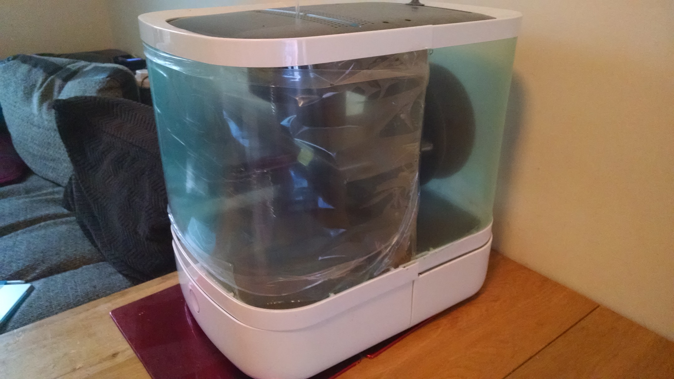
- Rear Hood: Using the parts from issues 82, 83 and 84 construct the rear hood. Unroll the hood plastic by removing the tape – as before, be careful as when you remove the last piece of tape, the plastic can unfold rapidly. Remove the supporting bars from both the top and bottom hood frames with the cutters from the v3 tool kit. Unroll the plastic from the top and bottom of the hood and orient so that the 8 hole side is at the bottom. Add four of the self tapping screws to the top frame and six to the bottom frame in the positions indicated, stopping just before they emerge into the space where the hood will fit. Slide the hood into the top frame, ensuring the hood holes align with the frame and tighten the screws. Repeat with the bottom frame and ensure that the hood is firmly within both the top and bottom frames.
The printer should now just be lacking the frame lifting mechanism which is provided in issues 85-90 and will be covered in the next post.