At the end of my last post in this series, we had added the print head to the main frame and created the filament spool. This post focuses on the top cover, filament guide and hood, covering issues 77-81 of 3D Create and Print by Eaglemoss Technology. If you’ve skipped a part of this series you can start from the beginning, including details of the Vector 3 printer I’m building on my 3D printer page. Some of these issues do not have build instructions but instead provide instructions on calibrating the printer and preparing for the first print, which I’ll cover in part 21. You will need all the parts from these 5 issues, but the instructions are in issues 77, 78 and 81.
-
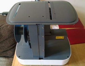
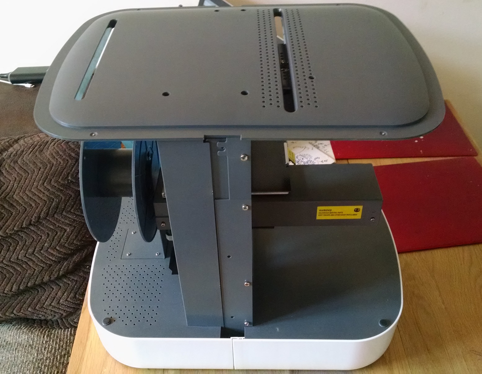
Top cover attached to main frame Top cover: Issue 77 comes with the top cover. Place over the main frame ensuring that the slot nearest the edge is over the filament spool holder. Align the bolt holes with those in the top of the main frame. Attach using the bolts for the three most centre holes, and the self-tapping screw for the hole farthest away from the centre.
-
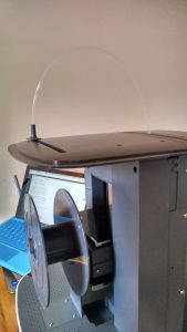
filament feeder tube attached to main frame Filament guide tube: Issue 78 comes with the filament guide tube and some pieces to put aside for later. Push the filament guide bottom through the gap in the top cover above the filament spooler and push the filament guide top on top of it from the top of the cover. Ensure that the guide assembly can move freely along the gap. Push one end of the filament tube into the guide assembly and the other end into the socket on the top of the feeder bearing block. As I’m saving the filament until I’m ready to print, I’ve skipped the filament feeding part. It’s obvious that any time there’s a need to change colour, there will be a need to feed the filament, so this isn’t a critical step, although I will keep issue 78 to hand in case I need to refer to it later.
-

Front hood assembled and placed on the printer for context Front hood window: Issues 79, 80 and 81 come with the components for the front hood frame and window. Remove the support structures from the hood frames, and remove the tape from the hood window. Be careful as you do this – when you take the last piece of tape off the window will unwrap quickly and you may either drop it or be hit in the face. Peel down the protective film by about 2cm from the inside and outside at the top and bottom. Take the top hood frame (which slopes inwards slightly) and align the elongated holes with the screw holes in the hood frame. This step can be a bit tricky with the very curved hood window and the more angular hood frame as the window doesn’t easily slide to get the positioning correct. Fix this in place with four of the self-tapping screws. Repeat this with the lower hood frame, ensuring the hood window is fully engaged into the frame and using the final 6 screws. At this point, the instructions say to remove all the protective plastic, but as you can see, I left it on and will remove it when I’m ready to attach the rear hood cover, parts for which come in issues 82, 83 and 84.

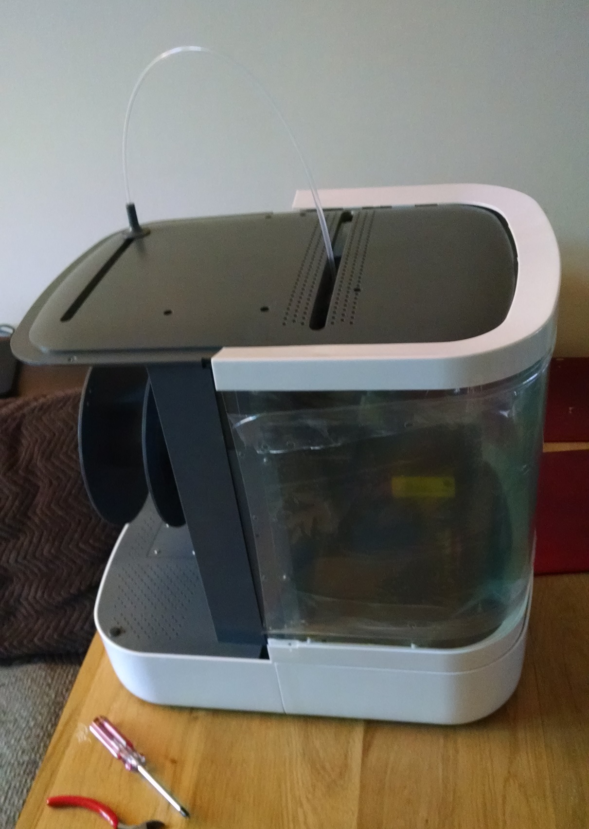
So, we now have a means of feeding filament through from the spooler to the print head and at least partial protection during printing, even if it’s not fully attached to the main frame.
In the next post in this series I’ll jump back to fitting the filament from issue 75 and go through to the first test print in issue 82.