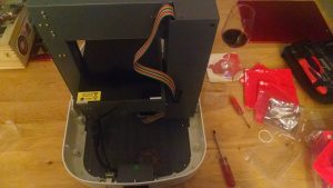
At the end of my last post in this series, we had added the USB, microcontroller and motor boards. This post focuses on the power module and fan covering issues 56-59 of 3D Create and Print by Eaglemoss Technology. If you’ve skipped a part of this series you can start from the beginning, including details of the Vector 3 printer I’m building on my 3D printer page.
-
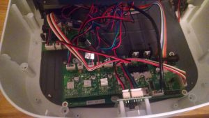
The fourth motor board is in Motor driver board: Issue 56 comes with the final motor driver board. This is a simple plug in the right way round while trying not to think about what motor this board is for…. (the print head feeder motor if you didn’t read the instructions 😉 )
-
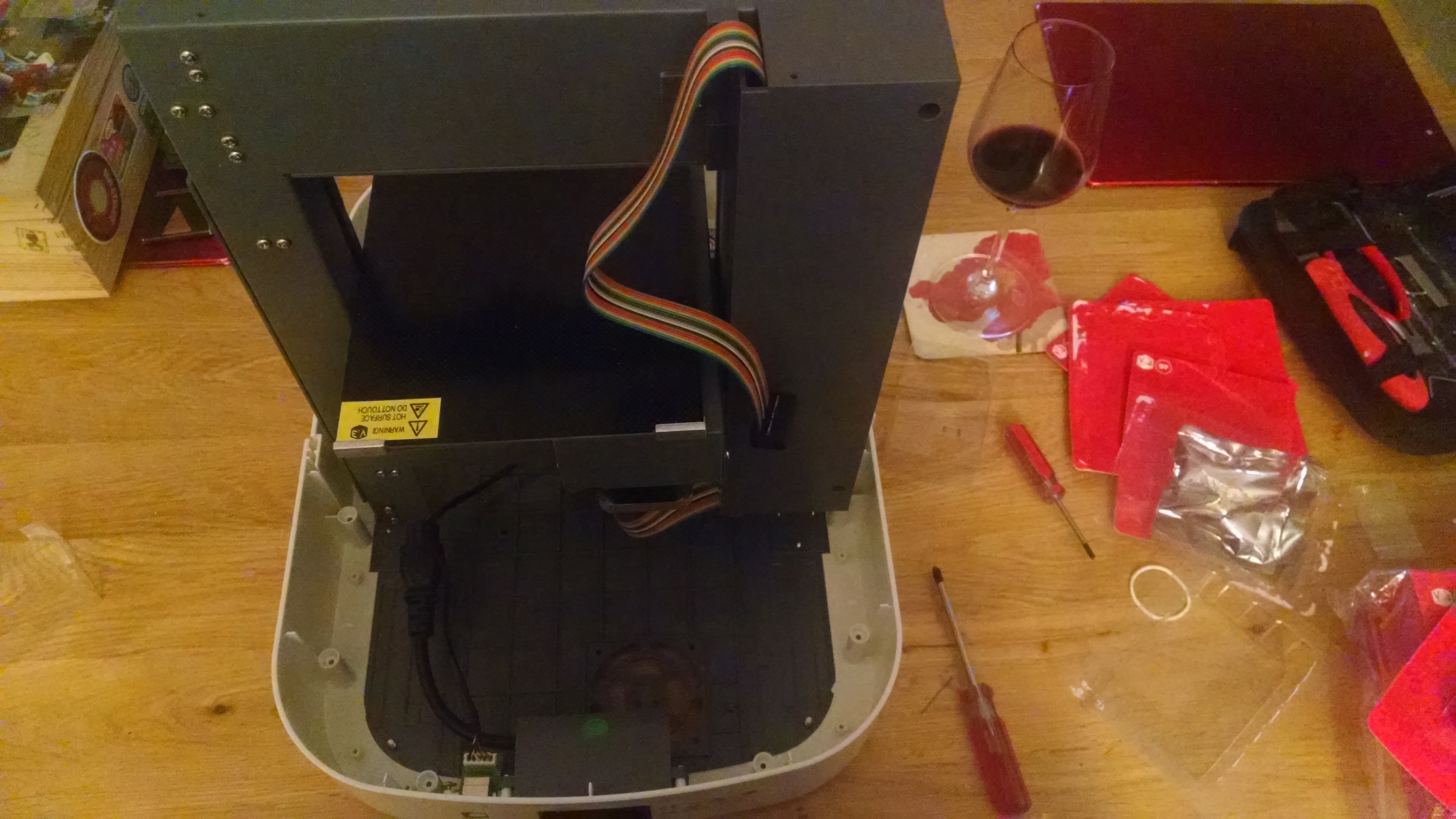
Print head ribbon fed through the casing with slack at the top Print head feeder cable: Issue 57 comes with what looks like a simple cable (which it is, although fitting it is not as simple). Plug one end of the cable into socket jp7 on the main microcontroller board. Pass the wire under the main frame. remove the four bolts from the main frame rear cover and pass the 16 wire ribbon cable through the slot at the top of the frame. Ensure all the wires are trailing through the gap at the bottom of the cover before reattaching the cover. Also make sure that none of the wires are caught in the frame as you reattach it.
-
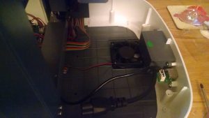
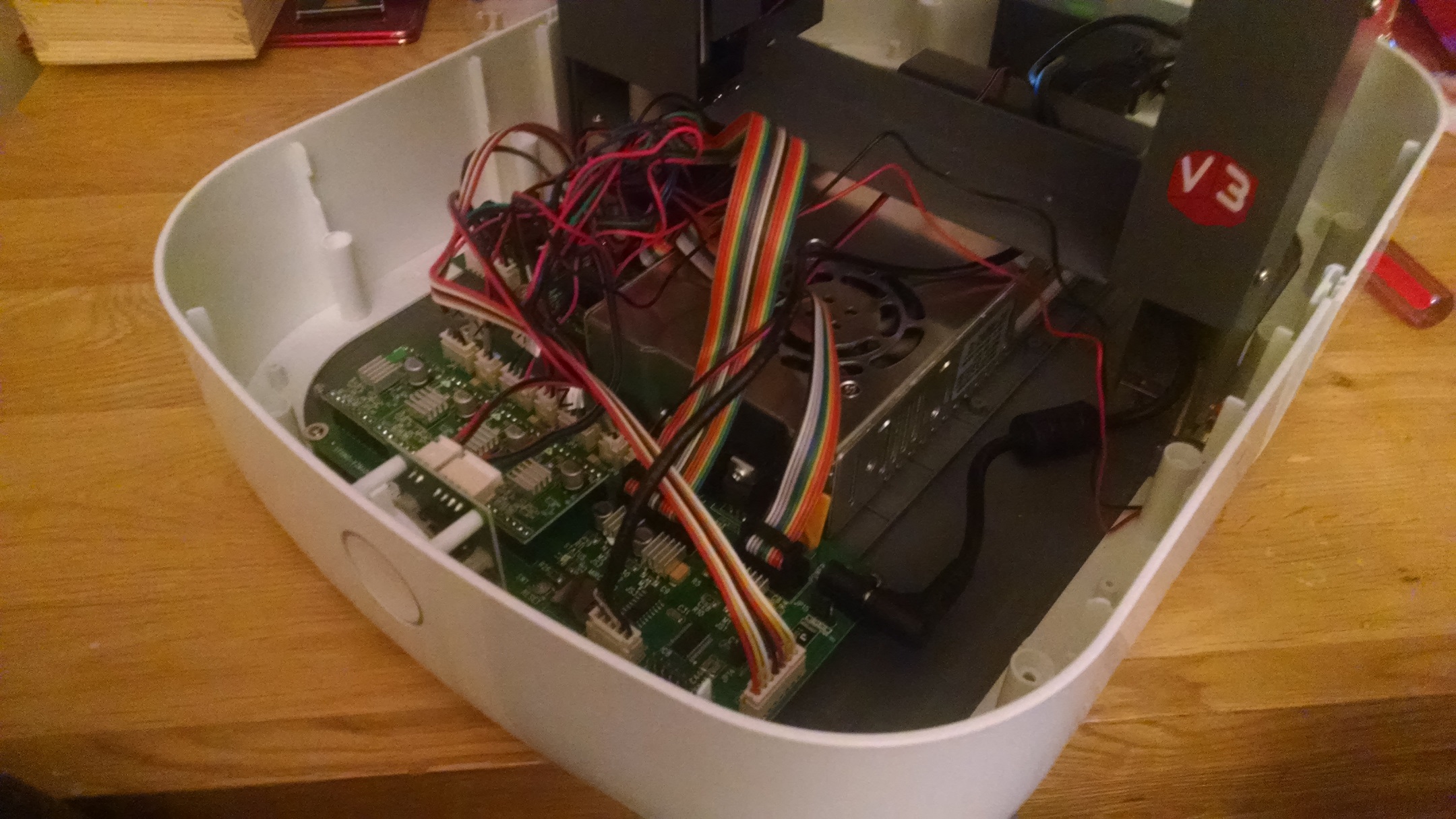
Cooling fan in place Cooling fan: Issue 58 comes with the fan for the lower rear cover. As for the USB board, the fan would have been a lot easier to fit had it been done before the power adapter. put the fan onto the air vents in the rear cover ensuring the blades are upwards and the power wire is facing the microcontroller board. Put the bolts into the holes on the fan and push through so they’re engaged. Gently turn the printer on its side and add the nuts to the underside of the printer, securing the fan. Finally plug the power wire into socket JP11 (marked fan) on the microcontroller board.
-
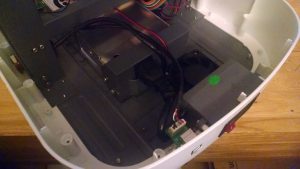
Power module at rear 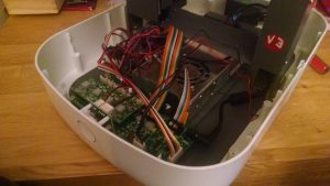
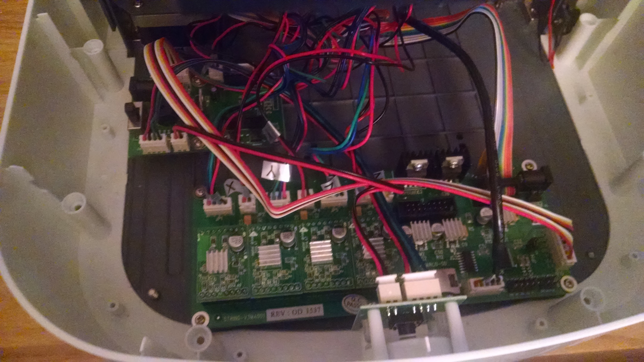
Power module at front with a mess of wires around it Power module: Issue 59 comes with a chunky box containing the power module. The first thing to do is tidy all the wires to the side so they don’t get trapped under the power module then slide under the main frame so that the fan end is closest to the microcontroller board. I found that this “tidying” was a relative process as with nothing to hold them in place they continually got in the way. The power module itself only just fits. Getting the plug from the mains power socket is very tricky as there is not much give in the wire and I can see why they ask you to do this before bolting the module to the frame. I found the fan wire kept dropping beneath the power module, but in the end I passed this over the power module just to ensure it was out of the way. Bolting the power module to the frame was easier than I expected as the hole alignment in the frame makes it simple to align everything and tighten in series. Finally push in the coaxial plug to the main microcontroller board.


So, just shy of 60 parts and we have all the external connectors, main power and main microcontroller board, all the motor boards and all the wires connected up. Obviously this all needs to be enclosed and we haven’t started on the print head yet. Given that issue 60 comes with the rear top plate to enclose all these wires it seems that we’re not far off from the business end of the printer…