At the end of my last post in this series, we had completed the heater plate and sensors and reconnected the y-axis covers. This post focuses on the z-shaft support and top and side covers, covering issues 40 – 43 of 3D Create and Print by Eaglemoss Technology. If you’ve skipped a part of this series you can start from the beginning, including details of the Vector 3 printer I’m building on my 3D printer page.
Unpacking this set of parts was a little disappointing to start with, however by the end, this covers the working parts and gives a device that looks like it’s not far from being ready to print…1
-
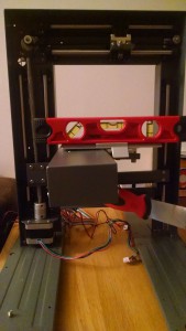
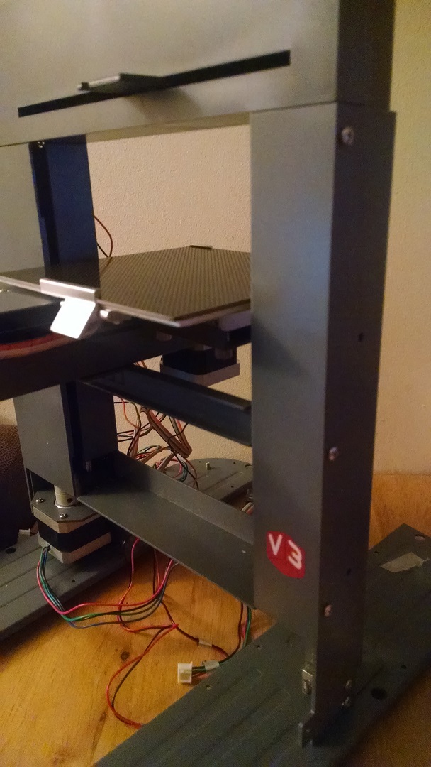
Connecting the y-axis assembly to the z-axis and checking it’s level. Note the use of the scraper tool to support the assembly. Z-shaft support: Issue 40 comes with a fairly innocuous looking bracket and 7 bolts. However, this piece is critical to get all three axes on the frame. The first step is to fit the y-axis assembly into the main frame. If you’ve been following my build, you’ll remember that I did not grease the z-axis shaft to avoid this gathering dust in part 9, so my first step was to do that. Even though this is in existing part, the instructions colour it yellow to show how the new parts fit together. The main thing here is to ensure that the six bolt holes align with both sides of the z-shaft bearing blocks (two for each of the three shafts). Once aligned, you can slide the z-shaft support bracket along the side of the y-axis, again making sure that the four holes align with the four holes in the bearing block and that then single hole is alongside the remaining hole in the y-axis cover. Add the bolts loosely and check that the y-axis is exactly horizontal2 – you may need to adjust the z-shaft bearing blocks to ensure that everything is level. Tighten all the bolts.
- Z-axis motor test: Using the motor test board from issue 7, connect the limit switch and motor then the AC adapter and turn on. Make sure that you can control the motor so that the y-axis assembly moves smoothly up and down the z-shaft. There’s a handy recommendation to leave the y-axis assembly about two thirds of the way up so that the circuit boards can be fitted.
-

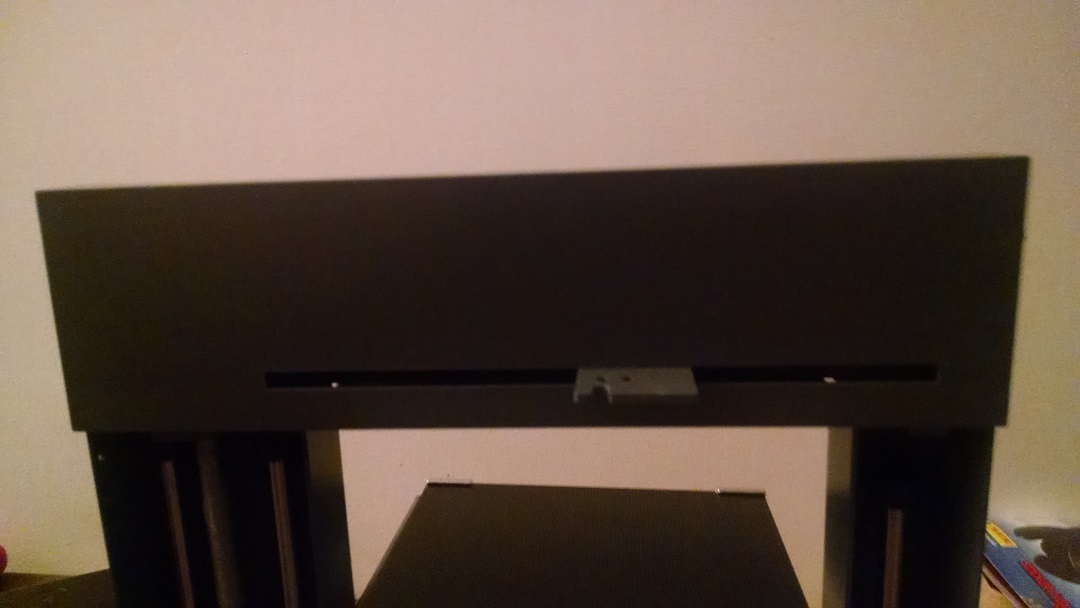
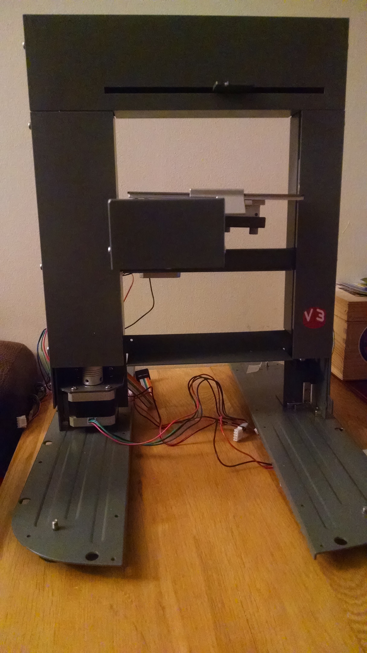
Top cover attached Main frame top cover: Issue 41 comes with a cover for the x-axis at the top of the main frame. This is a fairly straightforward step – the cover will only go on one way and secure the cover with the two bolts provided. The printer head will move freely through the slot in the cover, which will be attached in a future issue.
-
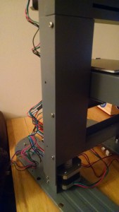
The side cover Main frame side cover A: Issue 42 comes with a cover for the z-axis shaft. This is also fairly straightforward and fast to fit to the frame. Make sure that the top of the side cover slots into the top cover and secure with the three bolts provided using only the holes towards the front of the cover. I found there was a slight gap between the top cover and the side cover once I’d aligned the bolt holes, but I don’t think this is anything to worry about. It’s nice to see the covers making a difference to the look of the printer.
-
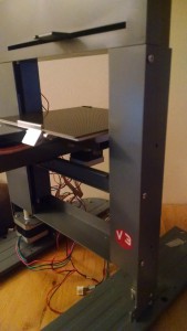
Second side cover Main frame side cover B: Issue 43 comes with a cover for the remainder of the z-axis on the right hand side. Slot the top of the side cover into the top cover as for the left hand side and secure with the three bolts. Again, use the three holes towards the front of the cover. With both of the side covers attached, make sure that there is enough of a gap on the inside of the frame for the y-axis assembly to move up and down. With all the covers on, now is a good time test the motors for all three axes and ensure they’re all moving freely.


So, at the end of these four issues, we’ve now tested all three motors and limit switches, and have all three axes secured to the main frame and covered. We’re still missing the third binder for the magazines, and the only clue for the next issue (44) is the rear cover. However, we’ve finally got something that looks quite considerable. I’m hoping that now that the covers are on, we’ll start moving towards something functional fairly quickly.