At the end of my last post in this series, we had attached the z-axis screw rod and made a start on the heater plate. This post focuses on the build plate, covering issues 36 – 39 of 3D Create and Print by Eaglemoss Technology. If you’ve skipped a part of this series you can start from the beginning, including details of the Vector 3 printer I’m building on my 3D printer page.
This set of issues also needs the heater sensor part from issue 35. Unpacking this set of four gives two study plates that will form the build base and lots of interesting looking wires.
EDIT: if you do not have the protection coil or strengthening strip and have a metal clip instead of a plastic one, do not worry. Eaglemoss upgraded these parts and delivered these for me with issue 70. If you are a few months behind then you may already have the better parts.
-
Build plate heater and sensor inserted Build plate heater: Issue 36 (and 35) provide the heater and sensor. You may remember that to keep the parts dust free (and avoid losing the bolts!) I put the cover back onto the y-axis, so the first step is to remove that and uncover the y-axis to get at the heater plate. The next step appears simple – slide the heater sensor and heater into the holes in the heater plate. However, this can be problematic if you’ve over tightened the springs, even by a millimetre, as the holes are tight and both the heater and sensor need to be perfectly parallel. All of the metal should be in the heater plate for these to be attached properly. In the end, I completely unattached the heater plate, inserted the heater and heater sensor and then reattached the plate to the y-axis. This was fiddly, but I felt that this was worthwhile to avoid forcing the sensor and heater.
-
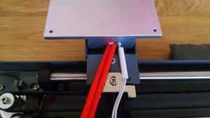
Wires protected with the coil and strengthened Protecting and strengthening the cables: Still with issue 36, wrap the protection coil around the wires. I found this east enough by opening the first turn of the coil and then twisting coil until it covered the wires. The strengthener strip was a little trickier, inserting this with the smooth side continually towards the wires required careful pushing to avoid pulling too hard on the heater and sensor wires and risk damaging them. The strengthener was longer than the protective coil so I decided to push it through to provide some support for the wires near the heater plate.
-
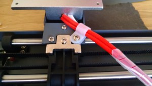
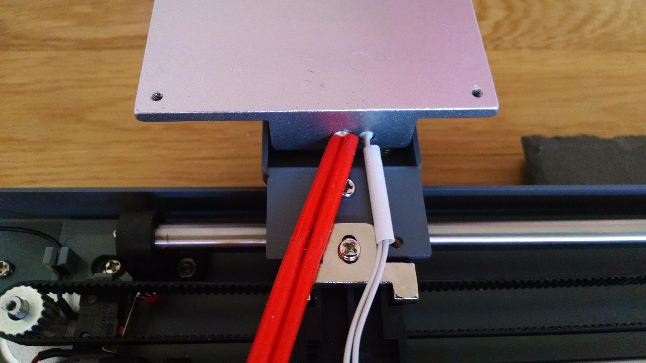
Cable clamp Cable clamp: The last part from issue 36 was to clamp the cables in place. There wasn’t much flex in the clamp to get the cables through and the washer headed bolt can be tricky to align – I loosened the other plate holder screws just to make sure that everything could be aligned and then retightened. This was the end of issue 36 and the two cabled ties (part 102) are needed with issue 37.
-

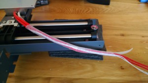
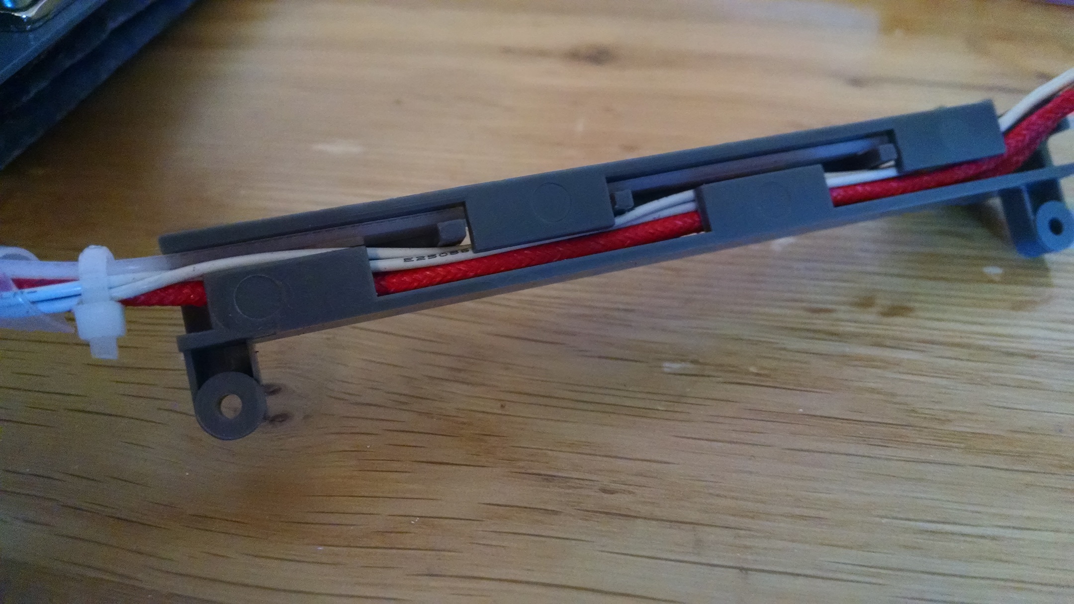
Cable holder Heater cables holder: Issue 37 asked to feed the strengthener through the heater cables holder. I found this really tricky and just couldn’t get the strengthener to fit through. I removed the strengthener from the protective coil, passed it through the cable holder and then fed it back into the coil. Because of how the wires had twisted in the coil, I put the heater wires in first and then then sensor wires. This is also a tight fit and I found my fingernails were very useful in just pushing the wires in (for those of you without fingernails 4mm longer than the end of your finger, the smallest allen key might be useful to help push the wires 🙂 ).
-

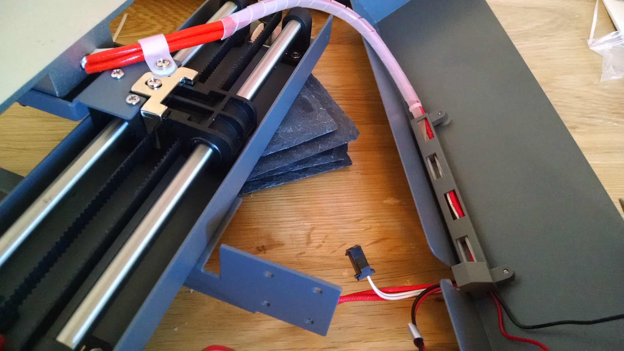
Adding the holder to the case 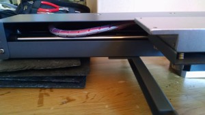
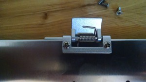
Y-axis case reattached – the wires seem low and movement is a bit stiff Gathering the y-axis cables: The second part of issue 37 combines these new cables with the y-axis limit switch cables, tidy the cables into the frame and put everything back together. The first step is to get the y-axis limit switch cables, feed them through the exit collar of the heater sensor cable holder and secure with a cable tie. Then attach the cable holder inside the y-axis cover, ensuring the bundle of 6 cables passes through the hole in the cover, and secure with the self-tapping screws. The instructions state to ensure that the wires are secured against the inside of the cover, but I don’t see how you can verify this. With the amount of wire and flex in the cable, I found that the coil did rest on the y-axis shafts and I couldn’t prevent this. I did gently pull the y-axis limit switch cables through the whole assembly so that they were clear of the mechanism as these were not protected. The instructions indicate to watch the video on thw website, but even logging in, these don’t exist anywhere I could find. I attached the cover plate and the mechanism is a bit stiff, but does move freely, I’ll keep an eye on this and if the video does appear, I’ll check and redo these steps if necessary. The final part from issue 37 was to attach the ribbon cable, making sure the heater sensor wires go into the brown and red wires and the heater itself plugs into the other 8.
-

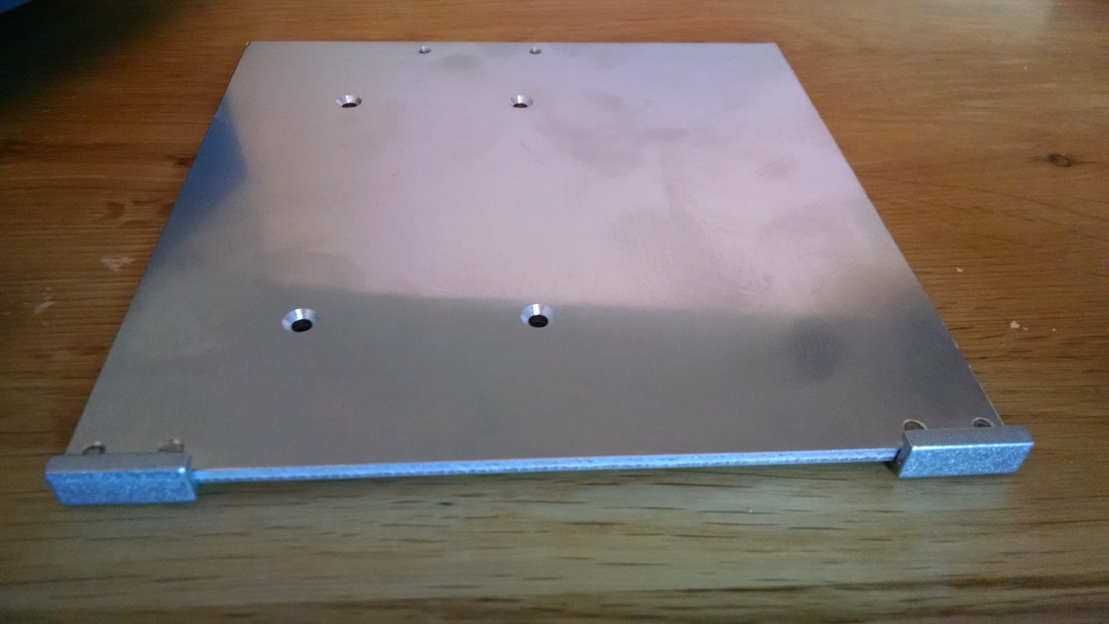
Build plate base Build plate base: Issue 38 comes with the build plate base and retainer clips and is a fairly simple step. Peel off the protective blue film from both sides of the base and place the plate so that the side with four holes is facing you and the four large holes are to the left (if you’ve got it the right way up then the large holes have the indentations to hold the screw heads). Add the retainer clips underneath the plate, ensuring the lipped edge is around the upper surface. Secure with two bolts. Repeat for the other retainer.
-
How I attached the spring clip 
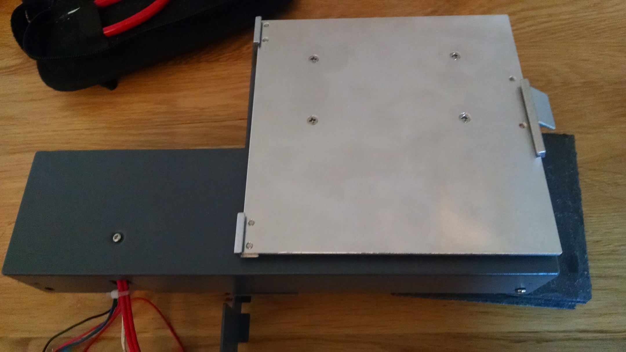
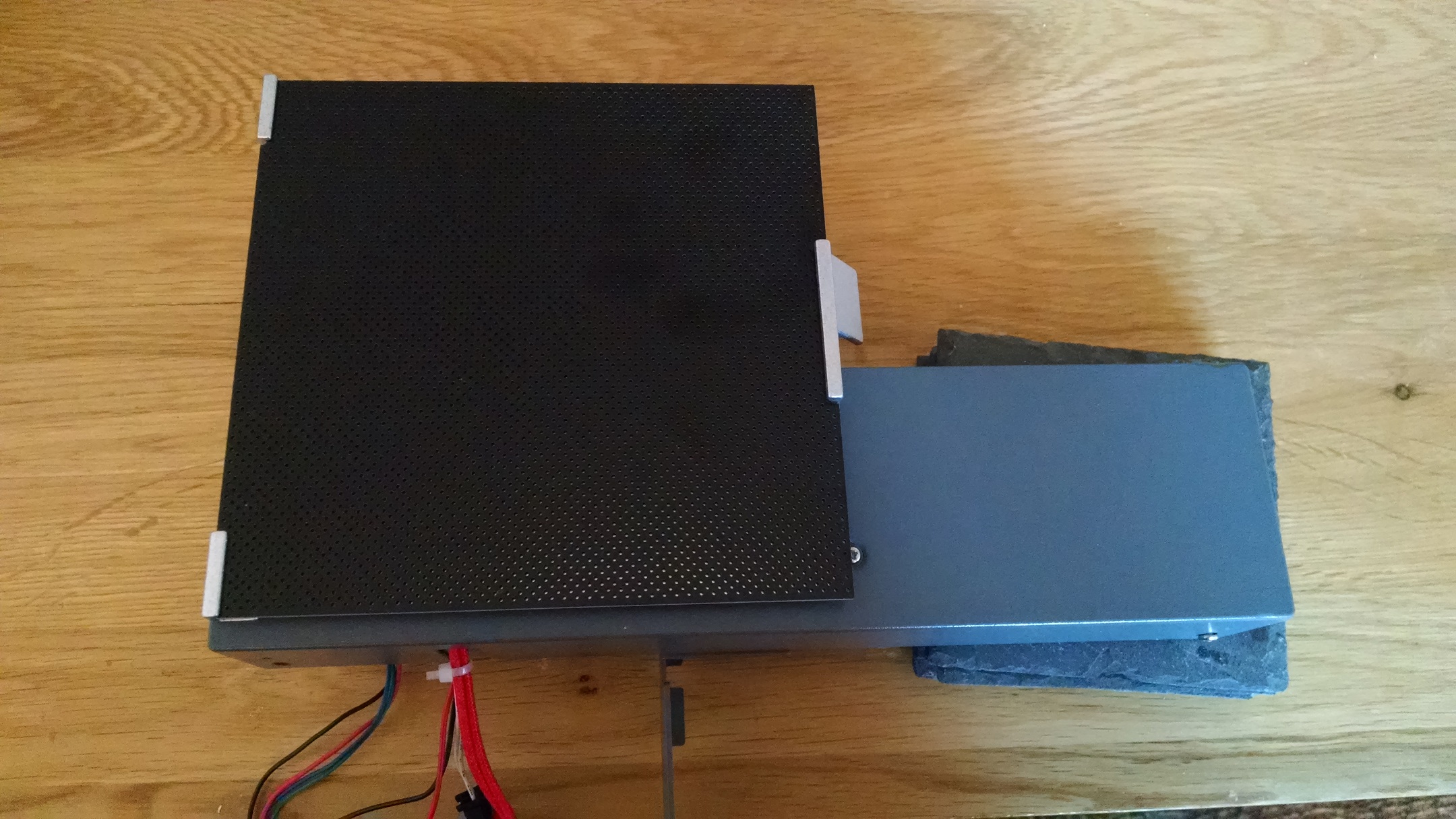
Build plate attached to the y-axis Build plate and clip: Issue 39 comes with a heat retardant sheet, bolts and clip. Using the plate base from issue 38, attach the spring clip to the remaining edge holes. It wasn’t clear, but I trapped one of the edges of the spring under the base plate as this gave a smoother spring action. Then, using the countersunk bolts, attach the base plate to the heat plate. Finally clip on the heat proof mat and adjust the sprung bolts to make sure everything is level.


So, we’ve now got a y-axis with heater, sensor and our build plate all attached, which is still separate from our main frame with the x-axis and z-axis. We’re also still waiting for a new binder. Issue 40 comes with a z-axis bracket, but there’s not much of a clue as to where the next few issues will take us.
Hi, love reading about another girl doing this build. The build videos are all on YouTube. The channel you want is eaglemoss collections
Hope this helps
hi Helenna
Thanks for reading. I’ll check their channel to see if I need to make some changed before I get too far ahead! How’s your build going?
It’s going well. I just wish I had more parts to put together. Every time I see it on my desk I want to do something with it lol.
I don’t think you will need to make any changes. It looks about the same as mine