At the end of my last post in this series, we had attached the z-axis motor and limit switch although hadn’t tested the action. This post looks at adding the z-axis screw rod and making a start on the heater plate, covering issues 32 – 35 of 3D Create and Print by Eaglemoss Technology. If you’ve skipped a part of this series you can start from the beginning, including details of the Vector 3 printer I’m building on my 3D printer page.
Opening up this pack and seeing parts with “heater” in their description was quite exciting – I know there’s still a way to go but I can’t wait to get some filament threaded through to a heater and start trying out some of the many free designs included with the magazines.
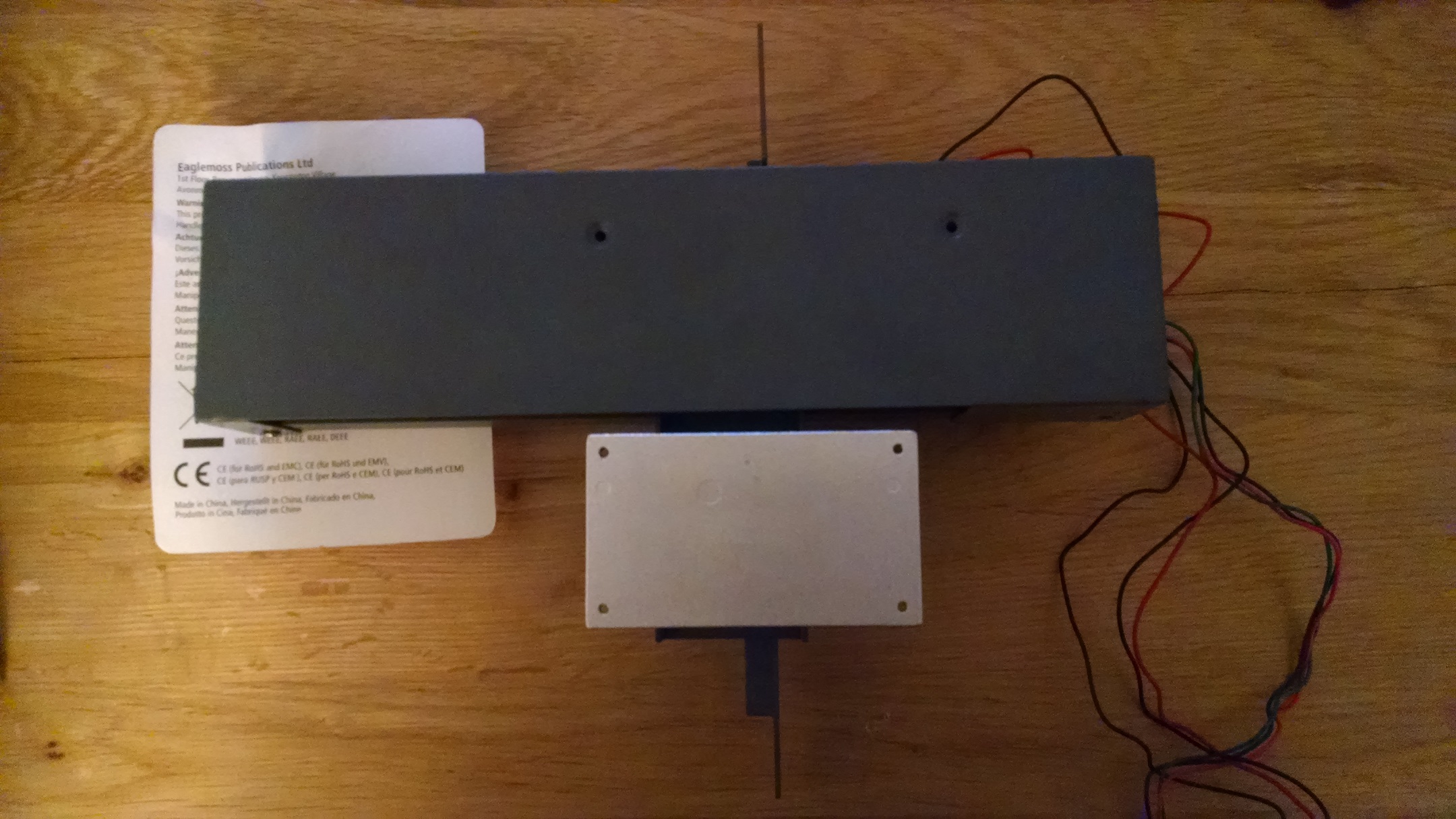
You may want to save the plastic bag that the magazines came in so that you can cover the printer after these steps.
-

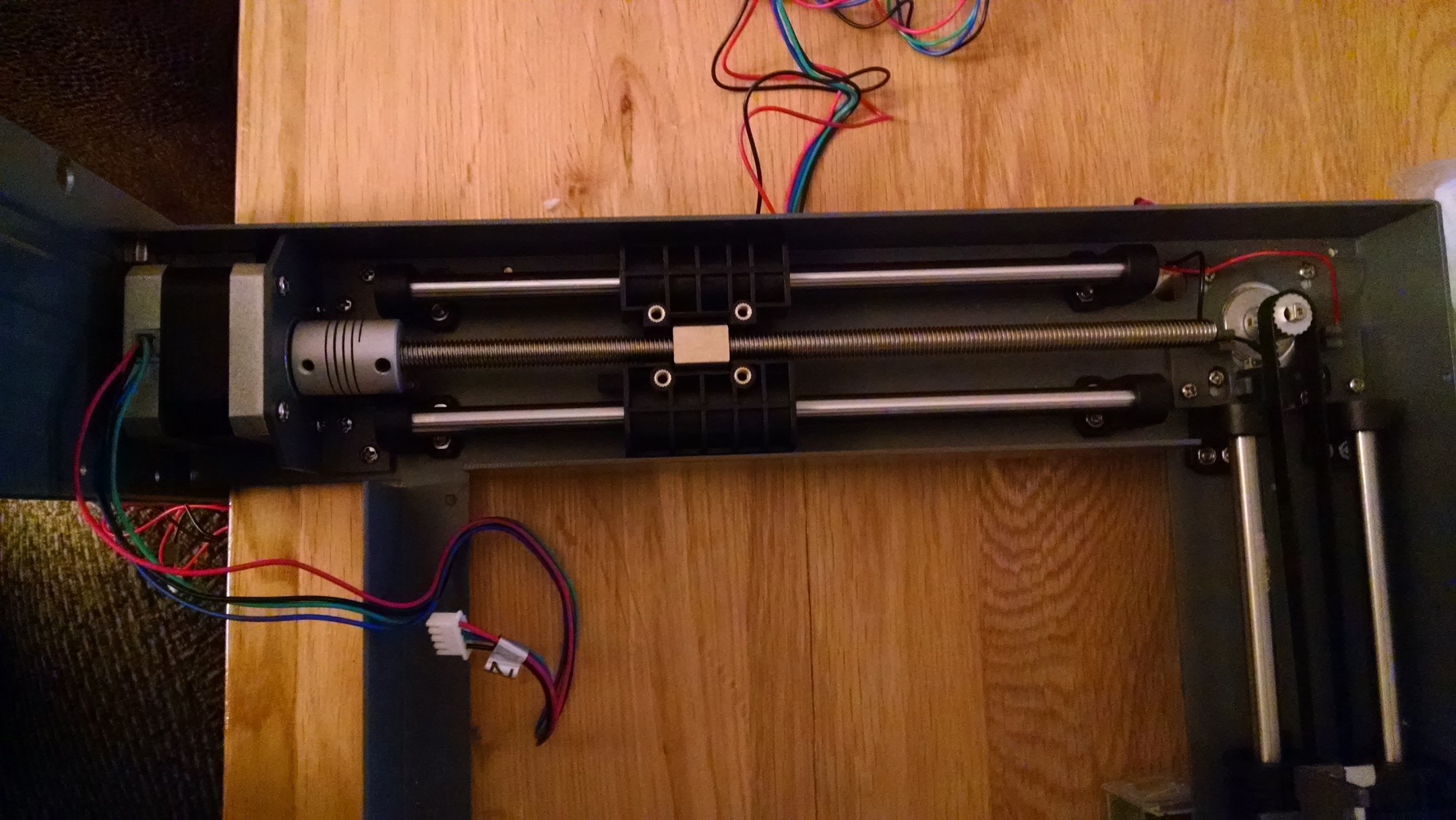
z-axis screw rod, ungreased and ready to be covered Z-axis screw rod: Issue 32 comes with the screw rod for the z-axis motor, justifying my decision of which way round to affix the motor coupling. This is a fairly simple step: thread the rod fixing block onto the rod until it is about one third of the way up. Push the rod fixing block into the socket on the centre of the bearing block and slide the block down until the rod is fully into the motor coupling. If you think it’s in, you may want to try turning the motor coupling in both directions – after a slight wiggle I got the rod to drop down a bit further. After tightening the grub screws as far as I could, I turned the hex key around so I could use the long arm as a level and managed to get a further 3/4 turn before it was truly as tight as it could be. With the grub screws fully tightened you notice quite a flex in the motor coupling – this is intentional and is due to the drilled hole around the coupling. The final step was to cover the rod with grease but I decided not to do this at this stage – the frame isn’t enclosed and I didn’t want dust/cat hair/stupid fruit flies getting into the grease. I covered the frame with a plastic bag so that the rod stayed clean and kept the cotton bud and bag of grease tapped inside the frame for later use.
- Heater plate: Issues 33 and 34 are needed together to start building the heater plate which attaches to the y-axis. The first step is to put the thumb screw through the heater plate holder and put a spring over each, which is simple enough. Then place the heater plate on top of the three screws and springs. This is very fiddly with a single pair of hands – the springs and screws don’t fit into the recesses in the heater plate and can easily slip out. The springs are also very firm, making it difficult to compress the holder and heater plate together to tighten the thumb screws. If you have some g-clips handy (or another person) to hold these in place then you might want to use them here. I also found a flat head screw driver was useful to tighten the screws. The instructions say leave a small gap but since the spacing isn’t important, tighten the screws so that the plate is parallel to the holder and the grub screw holes are not obscured. Add the three grub screws and tighten although, since we may have to adjust the spacing later I didn’t over tighten.
-
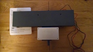
Heater plate attached to y-axis. I’m still using one of the old boxes to balance the y-axis motor while I work. Attaching to the y-axis: With the heater plate assembled we need to get the y-axis and remove the cover. Normally I’d leave this step until I had all the parts, but the screws from issue 34 were loose and I didn’t want to lose them. After removing the cover from the y-axis, screw the heater plate to the y-axis bearing block with the two bolts provided. I didn’t want to store the cover and screws, so I reattached them to keep them safe knowing I’d have to unscrew them next time, but this is a quick and easy step.
The heater sensor in issue 35 has to be kept safe until we have issue 36 and 37 which will be in the next drop, so that’s all we can do for now.
So we have one part safe, and the y-axis which will need reopening and more work doing to the heater plate. Also we have the z-axis screw rod ungreased. These seems like a safe adjustment of the instructions until next time. If you’ve got the binders, you’ll also have 5 loose issues now, so I’m hoping that another binder comes with the next drop.
For now, it’s back in the garage and 4 weeks until I get the parts.