At the end of my last post in this series, we had started the z-axis assembly and had paused ahead of adding the second z-axis bearing. This post looks at adding the z-axis bearing, motor and limit switch, covering issues 28 to 31 of 3D Create and Print by Eaglemoss Technology. If you’ve skipped a part of this series you can start from the beginning, including details of the Vector 3 printer I’m building on my 3D printer page.
Depending on whether you attached the z-axis shafts from issue 27 or put them to one side as I did, you may have to start by unscrewing the fixing bases and removing the shafts leaving only the top fixing bases attached to the frame. The instructions below assume that you’ve done this.
-
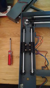
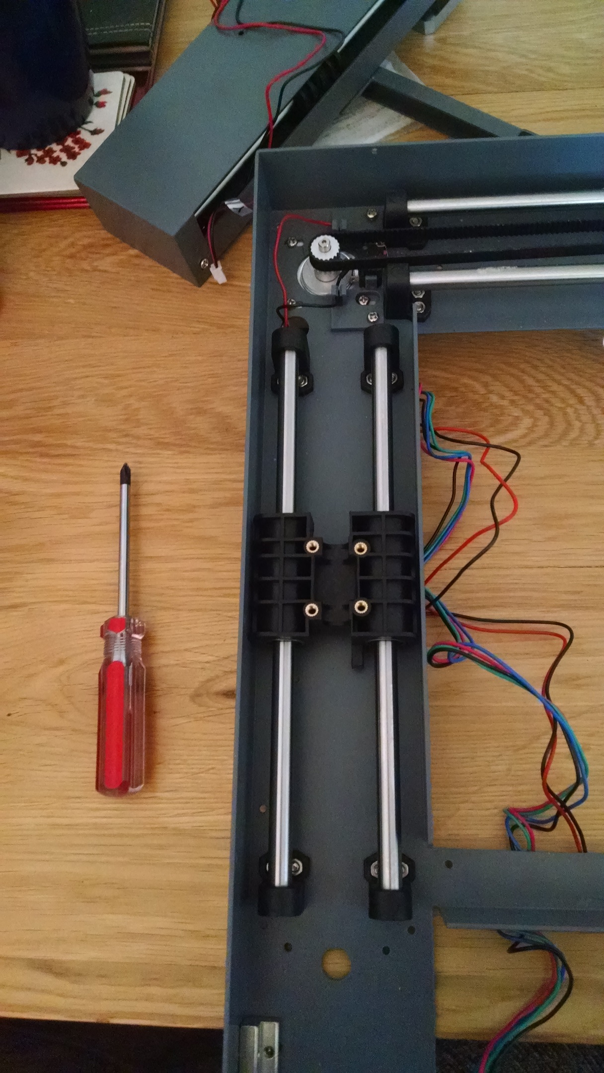
Bearing block on the z-axis shafts Z-axis linear bearing: Issue 28 gives us the linear bearing block for the main z-axis shafts. Slide the two shafts through the bearing block. Ensure the frame is led down and fit the shafts to the two top bases. The bearing block has a plastic ‘stopper’ for the limit switch and this needs to be on the bottom right. Make sure you get this the right way up else you’ll be fiddling with unscrewing bases and cursing later on. Fit the bottom two bases and ensure all the screws are tightened, making sure the block slides smoothly.
-

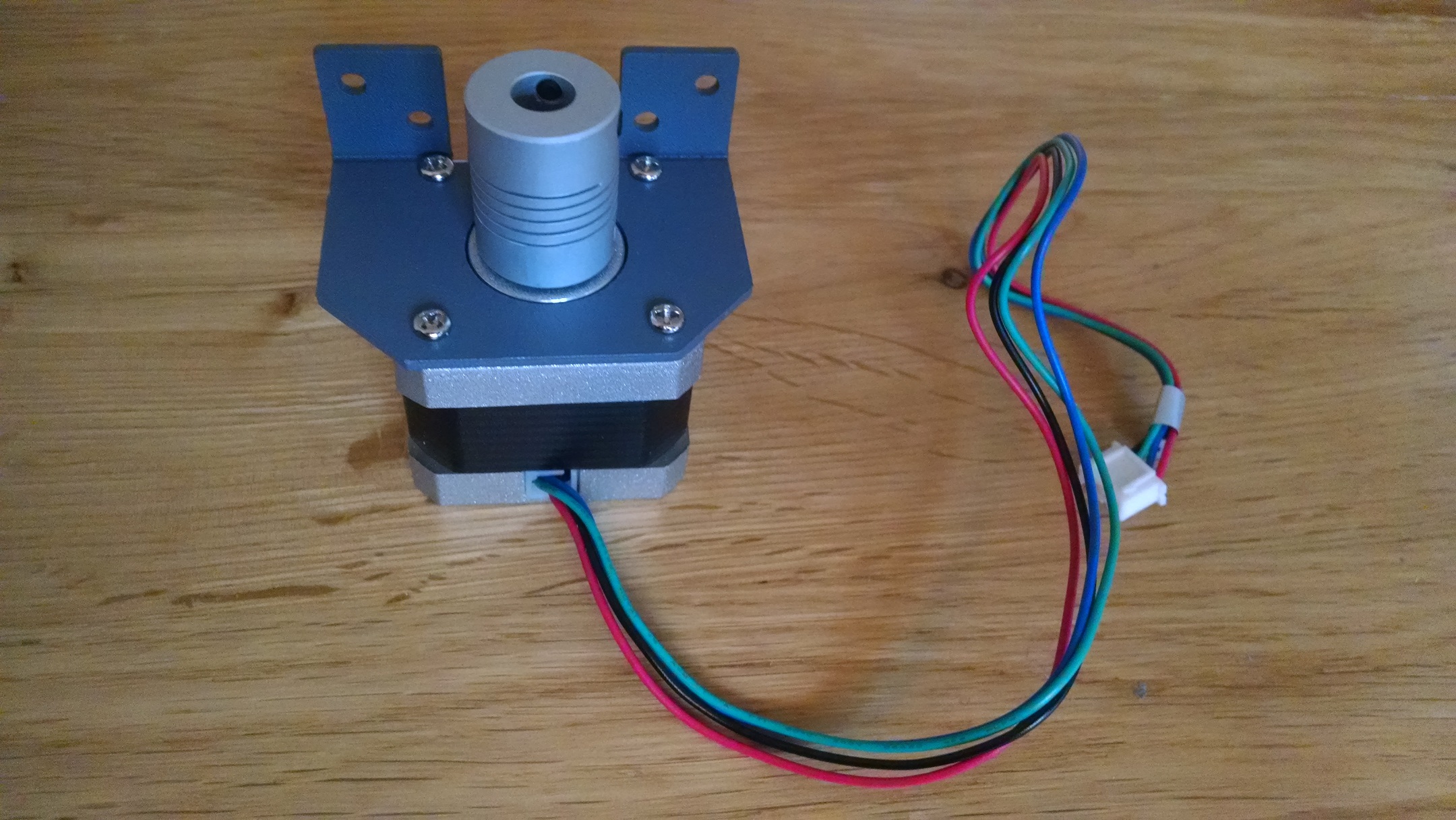
Z-axis motor Z-axis motor: Issue 29 provides the motor itself, but you need the motor mount from issue 30 before you can do anything with it. Yet again I’m pleased I get the magazines in a set of four so I can make progress rather than waiting :). The first step is to fit the grub screws. After a short but panicked search where I could only find bolts, I actually read the instructions in the magazine that said they “may be supplied pre-fitted into the drive shaft coupling”, which they were. The drive shaft coupling has a narrower end that just fits over the motor spindle and a wider end with no instructions as to which way up it should go. Given that the instructions indicate we will be adding a screw rod in a later issue (of unknown size) and that this will be tightened using the grub screws it seems like a fair assumption that the tighter fitting end should go on the spindle. There is also an instruction to leave a “small gap” to the motor. I left a 1mm gap (approximately) which seemed reasonable. The next step is to add the motor mounting bracket, making sure the central flange is pointing down and on the opposite side of the motor to the wires. Add the four screws and tighten.
-

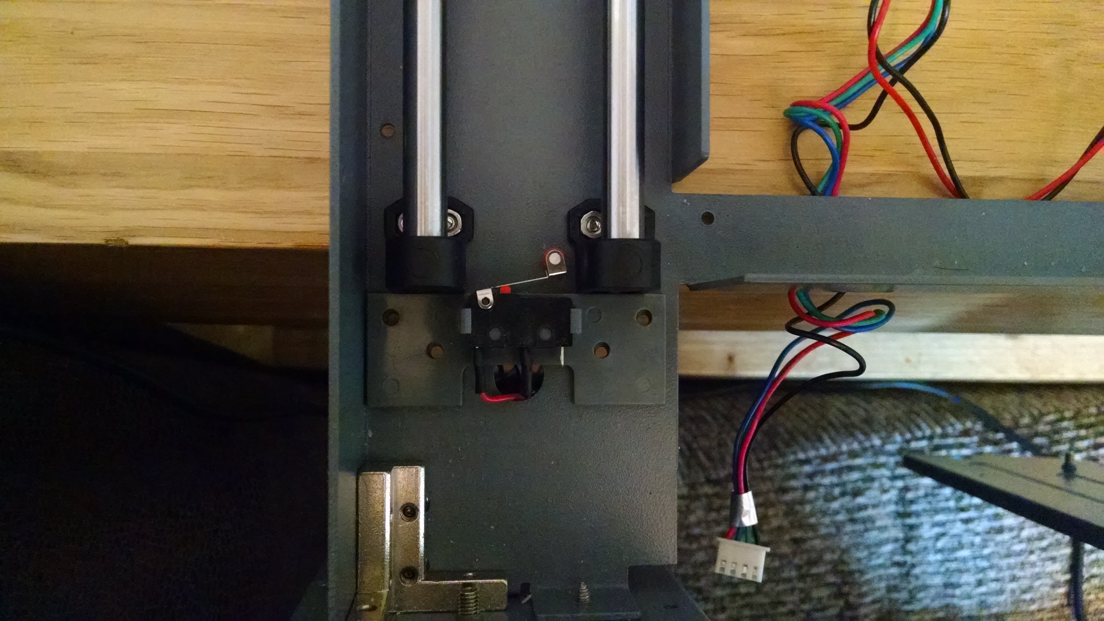
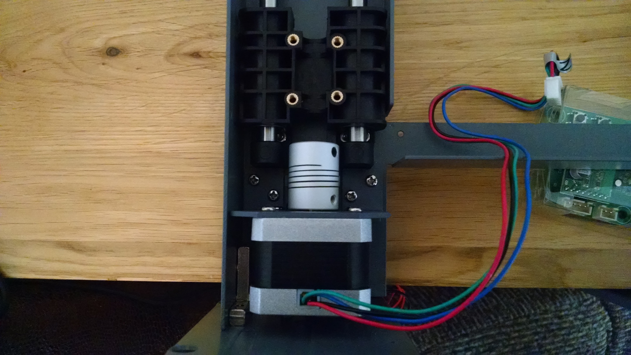
Limit switch in place Z-axis limit switch and attaching the motor: Issue 31 comes with the z-axis limit switch that fits beneath the motor. Attach the switch to the holder making sure that the red wire is on the left and the black on the right. Feed the wires through the hole in the frame and align the screw holes in the holder with those in the frame. This is easier if the bottom of the frame is hanging over the edge of your work surface. Move the bearing block out of the way to give yourself some space and carefully lay the motor over the limit switch. This is a little fiddly as you have several things in the way: one of the screws from the feet of the frame is where you’d naturally what to put the motor, plus the frame support makes it feel like it’s not sitting neatly. Persevere and you’ll get everything aligned. Be ready with the bolts. Fit them loosely to start with as the alignment is fairly precise and if you over-tighten one you’ll give yourself a hard time for the rest of them. Once all four are in place, tighten and then slide the bearing block to make sure that this touches the toggle of the limit switch.
So, there’s obviously more to do with the z-axis as we don’t yet have a means of propelling the bearing blocks, so getting the test circuit board out as soon as I saw the motor was probably premature :). With issue 30, you will also have filled your second binder – if you want a reminder of how adding magazines to the binder works then have a look at my first post.