So, in my last post we completed the Y-axis motor assembly and tested it. Issues 11-15 of the 3D Create and Print magazine will see us add the cover and bracket for the y-axis and start on the printer plates and feet. If you’ve skipped a part of this series you can start from the beginning, including details of the Vector 3 printer I’m building on my 3D printer page.
-
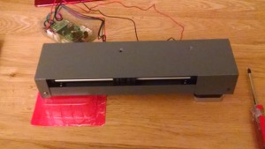
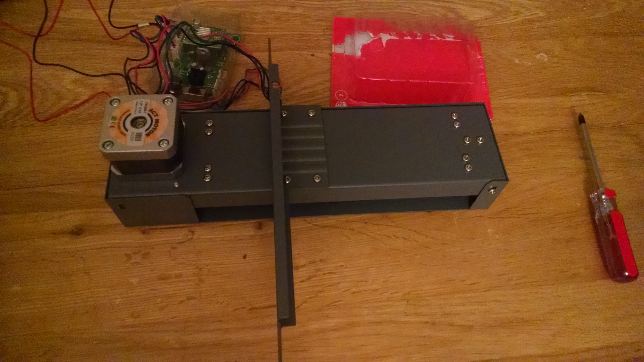
Y-axis cover Y-axis cover: This is a fairly simple 3-bolt step. The only real gotchas here are to ensure that the cover is on the correct way round (so the slot in the cover is closest to the motor) and that the wires from the limit switch are not caught in any of the other parts and thread out through the slot. Yes there are only meant to be three bolts at this stage 🙂 This is also one of the first bad designs I’ve noticed – the y-axis could benefit from an extra clip to secure the limit switch wires because, now they are hidden, they could easily be too close the the motor belt and get worn down. Should the printer stop working, this will be one of the the first things I check.

-

Y-axis bracket Y-axis bracket: I was hoping that this would mean I could throw away the box from issue 7 that I’d been using to support the assembly, but no – this step isn’t enough to support everything. This is another simple step – flip the assembly over and attach the bracket with the bolt provided. The whole Y-assembly can be put to one side for a while, even though the motor bearing isn’t actually connected to anything just yet!
-
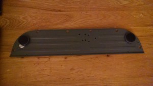
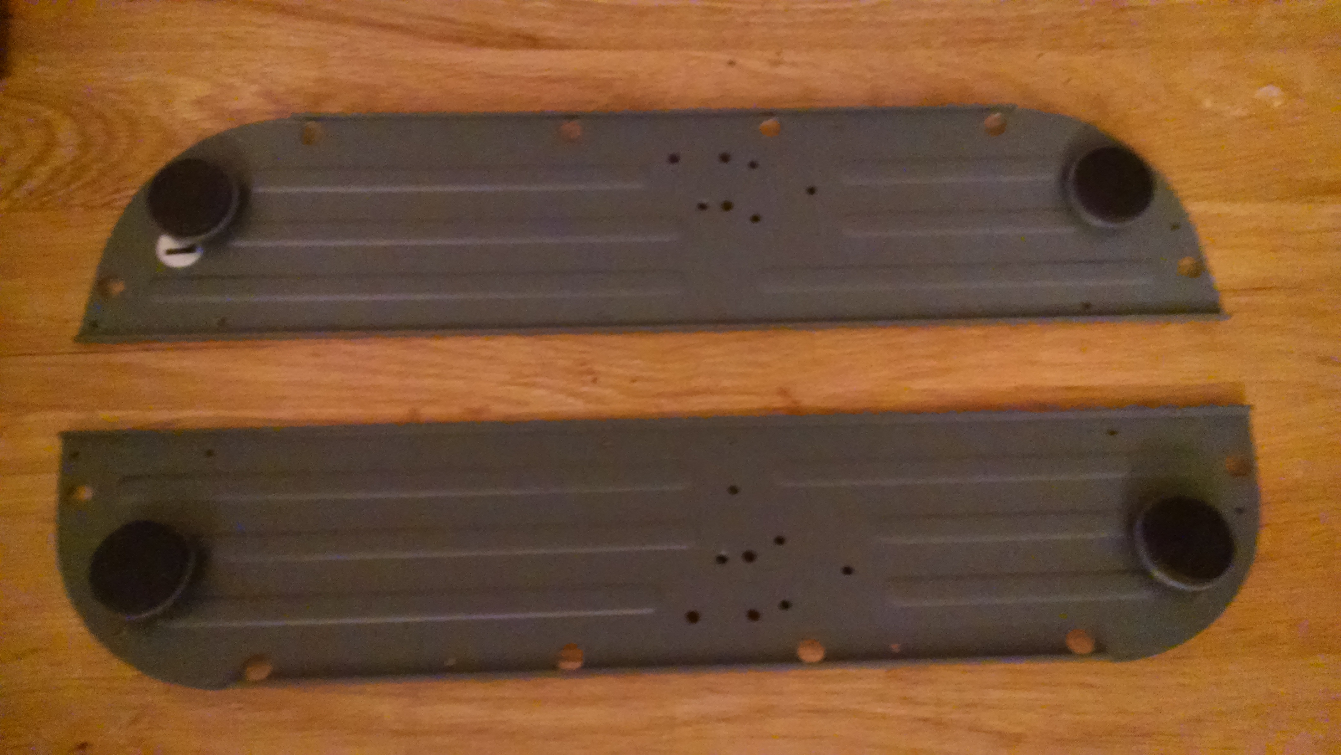
Left bottom plate Left bottom plate: Even though you only need two feet at this point, three are supplied with the instruction to keep one safe for later – somewhat inconsistent as in other issues, either the part has not been supplied until we need it (bolts) or the instructions have asked us to attach the part and then unattach it at a later step. However, the first thing to do is to stick the pads onto the feet. This is harder than it should be as the pads are a perfect fit and unless you are very precise you’ll need to use your nail or similar just to push the edges in. Screw the feet in fully, these can be adjusted later to make the printer sit flat on its final surface.
-
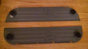
Left and right bottom plates Right bottom plate: This is exactly the same as for the left bottom plate, and you will now have two spare feet. It’s at this point with these base plates side by side that you get the first real feel of the footprint of the printer when completed. Even with more width between the plates this is a nice desktop-friendly size.
-
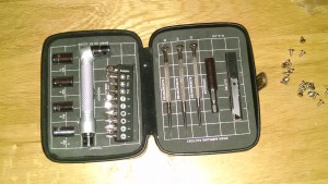
Essential for any girl’s handbag 😉 
Main frame and base plates Main frame: This is quite exciting as in addition to the base plates, the main frame gives us the height of the closed printer and an idea of the working area.. The first step is to attach brackets to the bottom plates. The diagrams aren’t overly clear on this but they will only fit on one way round (assuming you have the base plates the correct way up of course 🙂 ). The screws are a bit tight and it’s at this point I regretted using my kit screwdriver for diy earlier in the day and damaging the drive head. Fortunately I have spares 🙂 Attach the main frame to the base plates. The instructions say to screw in from underneath first, but unless you have an extra pair of hands it’s easier to leave it free standing and use the bolts to attache to the L brackets first and then turn the whole thing over and attach from underneath. The self-tapering bolts can be a bit annoying as they constantly feel cross-threaded but persevere! Finally, add your two spare feet and marvel at the skeleton of the printer!


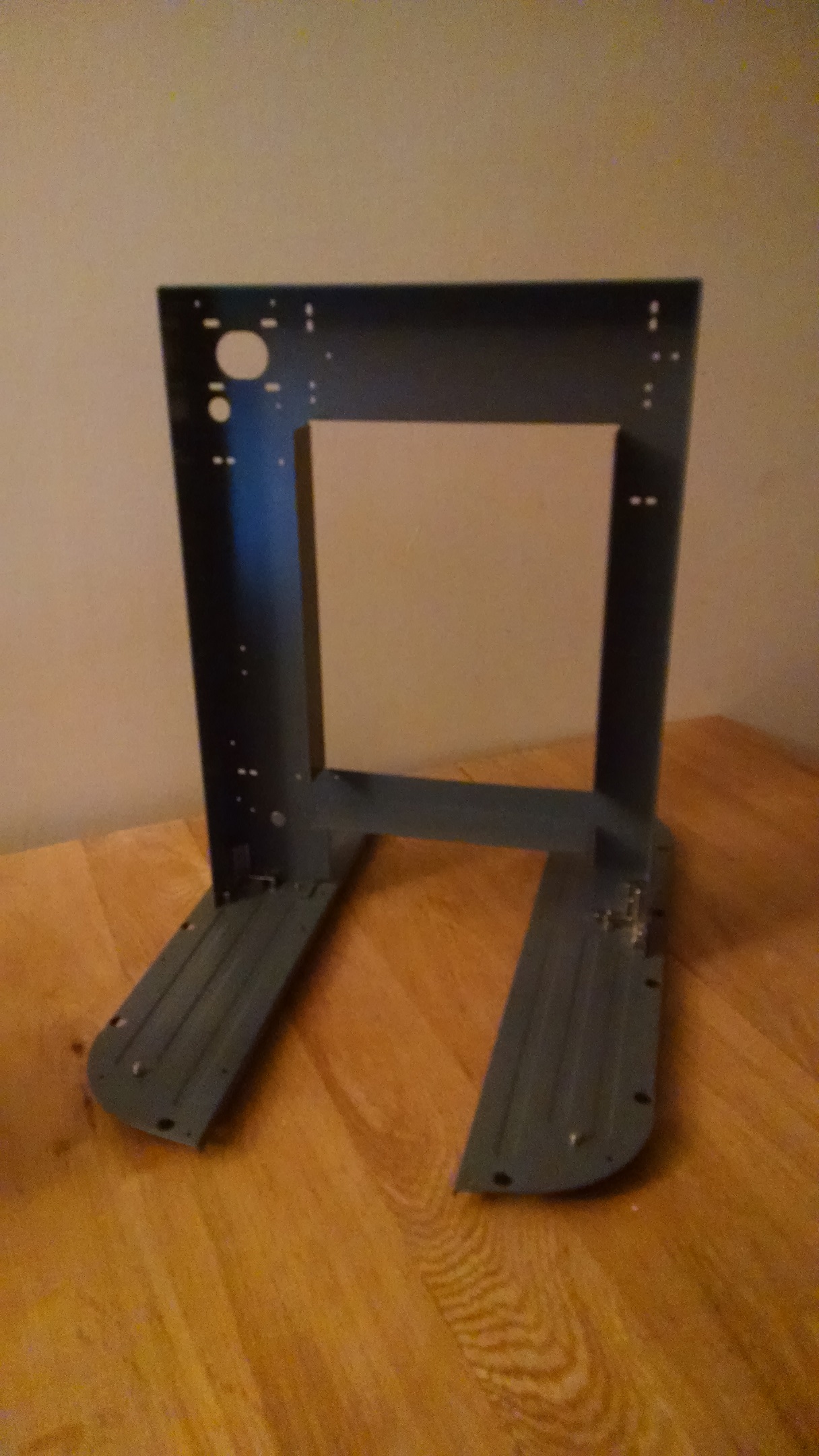
If the holes in the top of the main frame look familiar then you’d be right – the top of the main frame is where the x-axis assembly will sit, which will be the focus of the next post.