Today I finally started unwrapping the pieces of my 3D printer. After the issues with getting the magazines into their binding, I have been putting this off until I had the time and space to work through it properly. I have 15 pieces to work through and this includes several circuit boards and a plug. This entry covers the first 6 issues of 3D Create and Print by Eaglemoss Publications where we create the y-axis assembly up to the point of being ready for the motor and power.
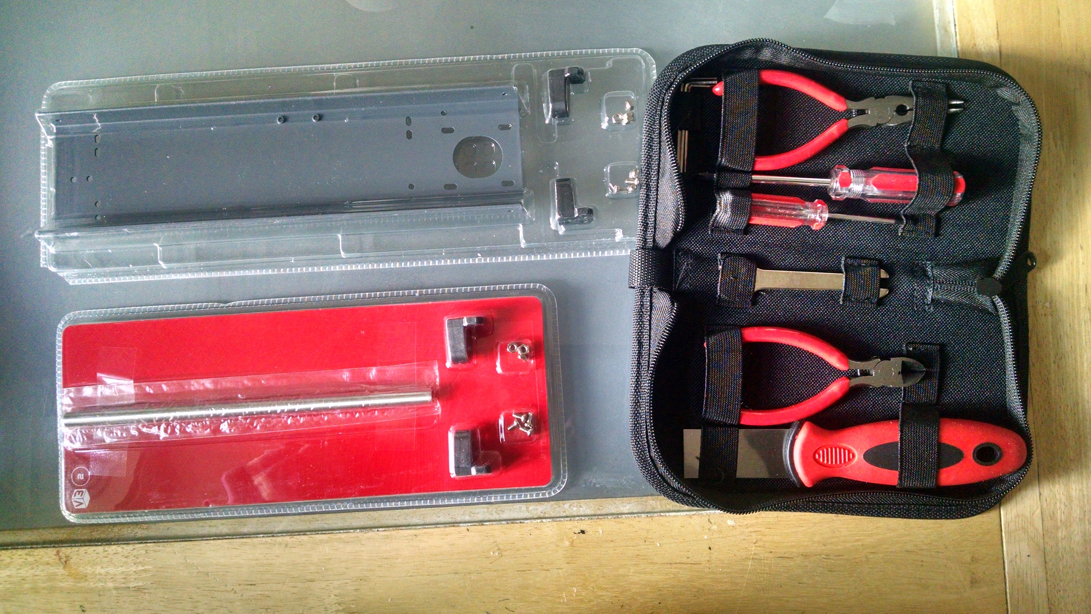
The last set of pieces also came with a handy tool kit with everything I need to build and maintain the printer – another reason that I hadn’t done this earlier – no matter how many screwdrivers or allen keys I’ve bought over the years, I can never find any when I need them. The one thing the tool kit is missing is a sharp pair of scissors to break open the plastic packaging of the printer pieces, but you can’t have everything!
-
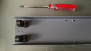
Issue 1 – bottom cover Y-Gantry bottom cover: This was a fairly sturdy metal base with two plastic fixers bolted to it. Nice and easy. Deceptively, this needs the larger of the two screwdrivers from the kit and, as with any kit – remember not to tighten the screws until it’s all lined up as it’s likely that we’ll be undoing these in a future step…
-

Issue 2: Y-axis shaft and base Y-shaft and fixing base: This provides the first of the shafts and the fixing bases for the other end of the base plate. The instructions say to fix both of the bases, but since you have to insert the rods and then fix the base, we’ll definitely need to unscrew these in a later step. The y-shaft is a very sturdy 8mm diameter steel rod. At this point, I’m impressed with the quality of the materials provided (although it is early days yet 😉 ). When adding the base at the other end of the shaft, I suggest putting the nuts into the base before aligning it under the rod – far less fiddly. Loosely affix the other base and that’s step 2 done.
-
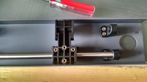
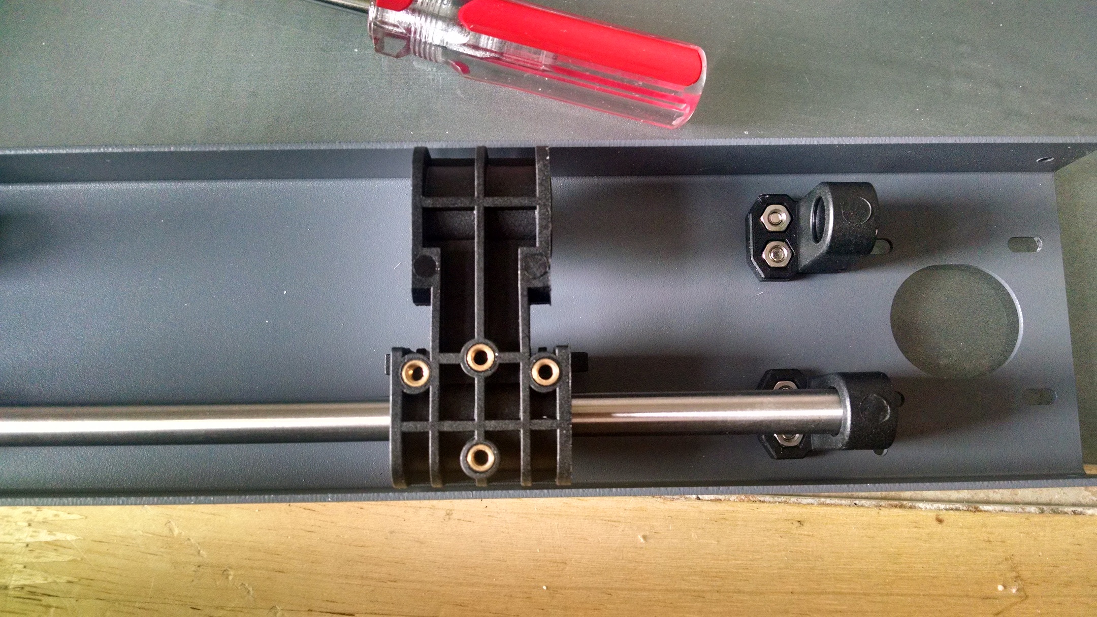
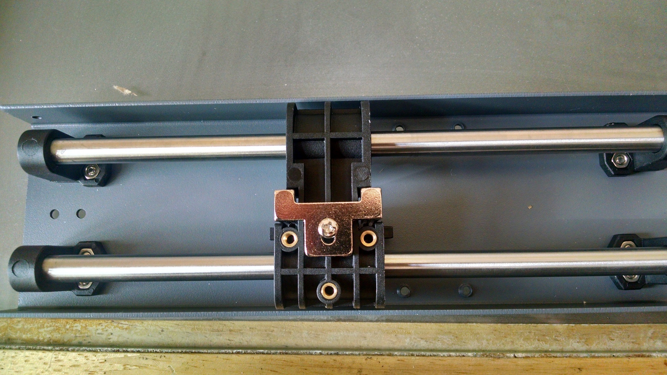
Issue 3: Y-axis bearing block Y-axis linear bearing block: Surprisingly enough, step 3 starts off with undoing the base plate you’ve already fixed to the shaft so you can add this part 🙂 . Other than the fiddliness and potential to lose a nut or bolt here, this is a simple case of unscrewing the base, slide on the block and refix the base. The block doesn’t slide as smoothly as I expected on the shaft, but I don’t know whether it is supposed to be loose or tight.
-

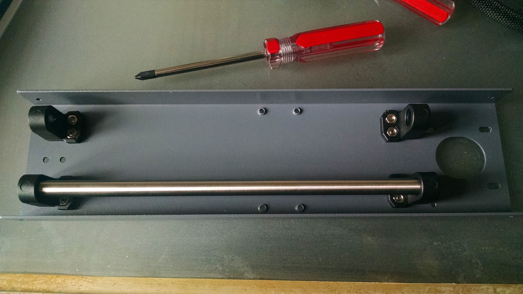
Issue 4: Y-shaft and belt holder Y-shaft and belt holder: Now we get our second shaft. The first thing to do is basically a repeat of step 2, but just for the other side. Make sure that the new shaft fits through the bearing block and refix the base. At this point, you’re asked to check that the block slides smoothly and to tighten all the bolts. Interestingly if it doesn’t then the instructions are to loosen the bolts until it does slide smoothly and then retighten them… which is about as helpful as “wiggle it a bit”. Thankfully, the block does slide smoothly now that the second shaft is in place. So the belt holder can be attached to the bearing block (loosely as we don’t have the belt yet…)
-
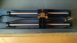
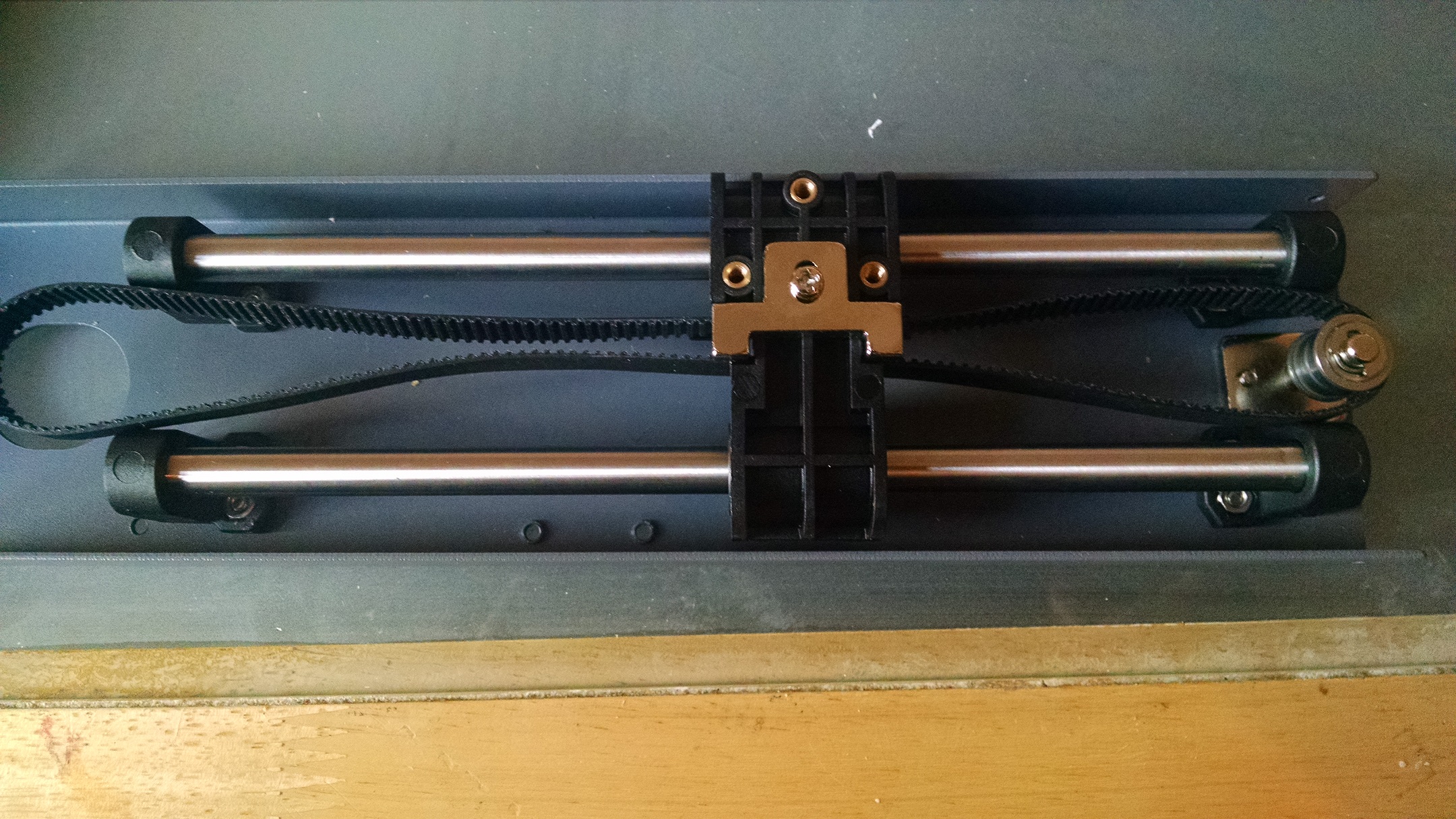
Issue 5: Bearing belt 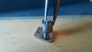
Issue 5: fixing the e-clip Bearing, base and timing belt: The first step is just to slide the two bearings over the base. Adding the e-clip in this step is really fiddly and you may want to wear eye protection for this step – I’m glad I did! The instructions suggest long-nosed pliers, but this doesn’t help much – I spent a while searching for this on the floor after it pinged off the top (and bounced off my glasses – had I not been wearing them then it could easily have embedded in my eye instead). In the end I used the long nosed pliers from the kit and held the e-clip from above with one side of the pliers against the shaft and the other on the other side of the clip and gently pushed. Then loosen the belt holder and add the timing belt so the grooves in the belt fit into the belt holder, tighten the screw and loop the belt over the bearings.
-
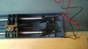
Issue 6: y-axis limit switch Y-axis limit switch: The first electronic component! Clip the switch into the holder (make sure it’s the right way up!), clip the red and black wires into the holder and screw the holder to the base plate with the bolts provided.


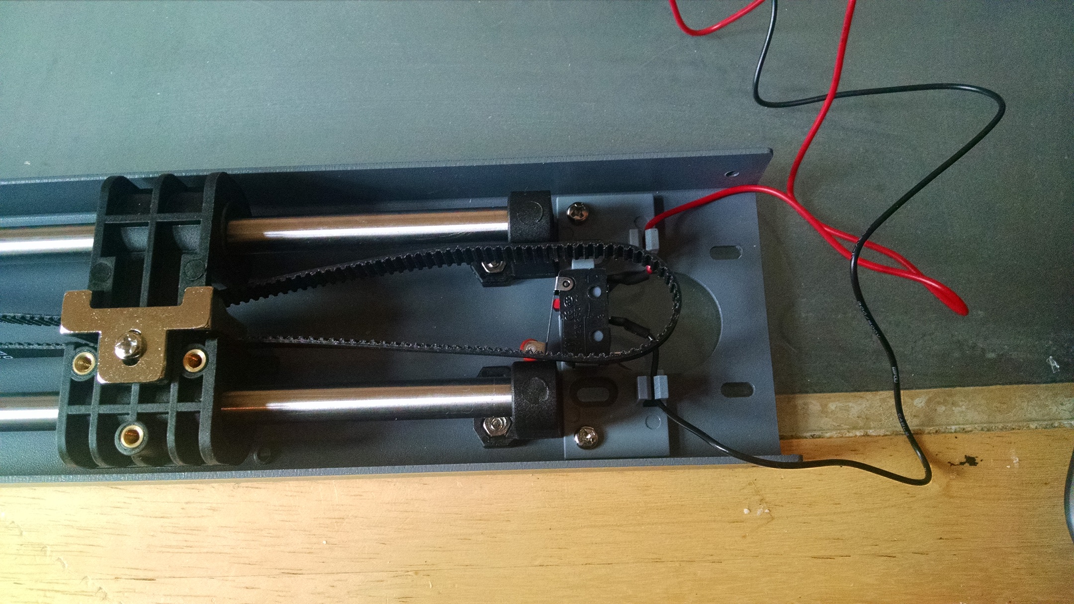
This completes the y-axis assembly with the exception of the motor, circuitry and power adapter, which I’ll cover in the next post.